INSTALLATION
Removal / installation · Vehicles built Aug 2005 – Dec 2005
Versions by build date: Aug 2005 – Dec 2005 from Jan 2006
| 1.
INSTALL FUEL INJECTOR ASSEMBLY |
 |
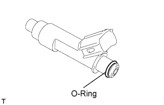
Apply a light coat of gasoline or spindle oil to new O-rings, then install one onto each fuel injector.
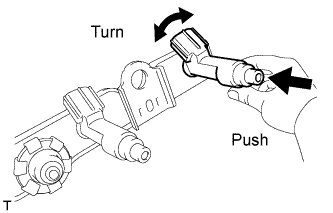
Apply a light coat of gasoline or spindle oil to the contact surfaces of the fuel delivery pipe and the O-ring of the fuel injector.
- While turning the fuel injector left and right, install it onto the fuel delivery pipe.
- NOTICE:
- Do not twist the O-ring.
- After installing the fuel injectors, check that they turn smoothly. If not, replace the O-ring with a new one.
| 2.
INSTALL INJECTOR VIBRATION INSULATOR |
|
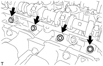
Install 4 new injector vibration insulators onto the cylinder head.
| 3.
INSTALL DELIVERY PIPE NO. 1 SPACER |
|
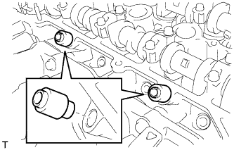
Install the 2 No. 1 delivery pipe spacers onto the cylinder head.
- NOTICE:
- Install the delivery pipe No. 1 spacer in the correct direction.
| 4.
INSTALL FUEL DELIVERY PIPE SUB-ASSEMBLY |
|
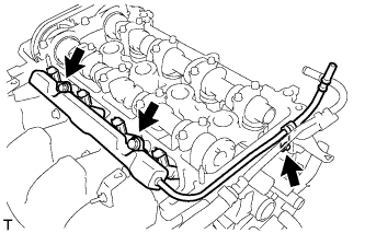
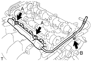
Install the fuel delivery pipe sub-assembly with the 4 fuel injectors, then provisionally install the 3 bolts.
- NOTICE:
- Do not drop the fuel injectors when installing the fuel delivery pipe sub-assembly.
- Check that the fuel injectors rotate smoothly after installing the fuel delivery pipe sub-assembly.
- Tighten the 3 bolts to the specified torque.
-
Torque:
- 19 N*m{
194 kgf*cm
, 14 ft.*lbf
}
for bolt A
- 9.0 N*m{
92 kgf*cm
, 80 in.*lbf
}
for bolt B
| 5.
CONNECT FUEL TUBE SUB-ASSEMBLY |
|
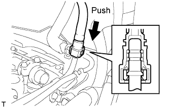
Insert the fuel tube connector into the fuel delivery pipe until a click sound can be heard.
- NOTICE:
- Check that there are no scratches or foreign matter around the disconnected parts of the fuel tube connector and pipe before performing this work.
- After connecting the fuel tube, check that the fuel tube connector and pipe are securely connected by pulling them.
- Install the fuel pipe clamp.
| 6.
INSTALL CYLINDER HEAD COVER SUB-ASSEMBLY |
|
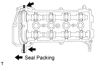
Apply seal packing to the cylinder head as shown in the illustration.
- Seal Packing:
- Part No. 08826-00080 or the equivalent
- NOTICE:
- Remove any oil from the contact surface.
- Install the cylinder head cover sub-assembly within 3 minutes of applying the seal packing.
- Do not start the engine for at least 2 hours after the installation.
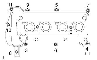
Install the cylinder head cover sub-assembly with the 9 bolts, 2 nuts and 2 seal washers.
- Tighten the 9 bolts and 2 nuts in the sequence shown in the illustration.
-
Torque:
- 10 N*m{
102 kgf*cm
, 7.0 ft.*lbf
}
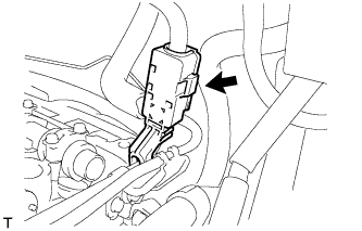
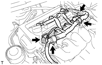
- Connect the connector and wire harness clamp as shown in the illustration and connect the engine wire harness.
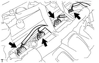
- Connect the fuel injector connectors.
| 7.
CONNECT VENTILATION HOSE NO. 2 |
|
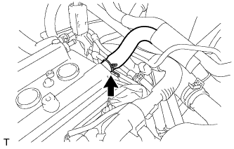
Connect ventilation hose No. 2.
| 8.
CONNECT VENTILATION HOSE |
|
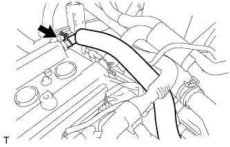
Connect the ventilation hose.
| 9.
INSTALL IGNITION COIL NO. 1
|
|
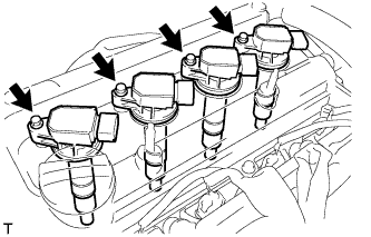
Install the 4 ignition coils with the 4 bolts.
-
Torque:
- 9.0 N*m{
92 kgf*cm
, 80 in.*lbf
}
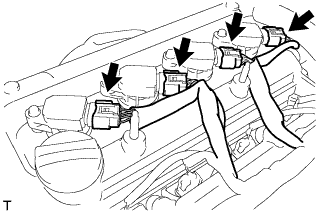
- Connect the 4 ignition coil connectors.
| 10.
CONNECT CABLE TO NEGATIVE BATTERY TERMINAL |
|
-
Torque:
- 5.4 N*m{
55 kgf*cm
, 48 in.*lbf
}
| 11.
CHECK FOR FUEL LEAKAGE
|
|
When using the intelligent tester.
Connect the intelligent tester to the DLC3.
Turn the ignition switch on (IG) and the intelligent tester main switch on.
- NOTICE:
- Do not start the engine.
Select the Active Test mode on the intelligent tester.
- HINT:
- Refer to the intelligent tester operator's manual for further details.
Check that there is no fuel leakage anywhere in the fuel system after doing maintenance.
| 12.
CHECK FOR ENGINE OIL LEAKAGE |
|
| 13.
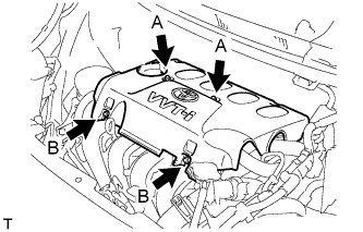
INSTALL CYLINDER HEAD COVER NO. 2
|
|
Tighten 2 A nuts, then 2 B nuts .
-
Torque:
- 7.0 N*m{
71 kgf*cm
, 62 in.*lbf
}