TERMINALS OF ECU
System information · Vehicles built from Aug 2005
| CHECK MAIN BODY ECU |
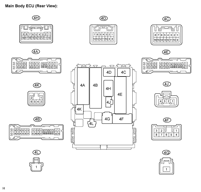

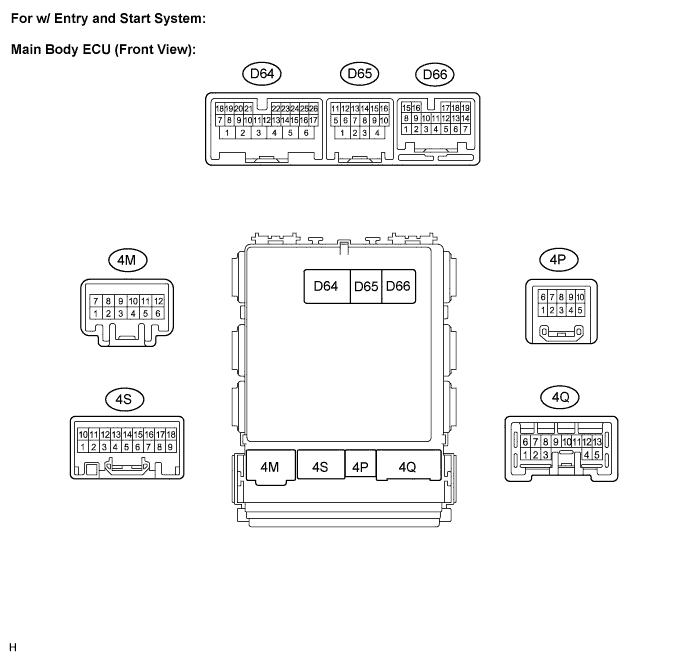
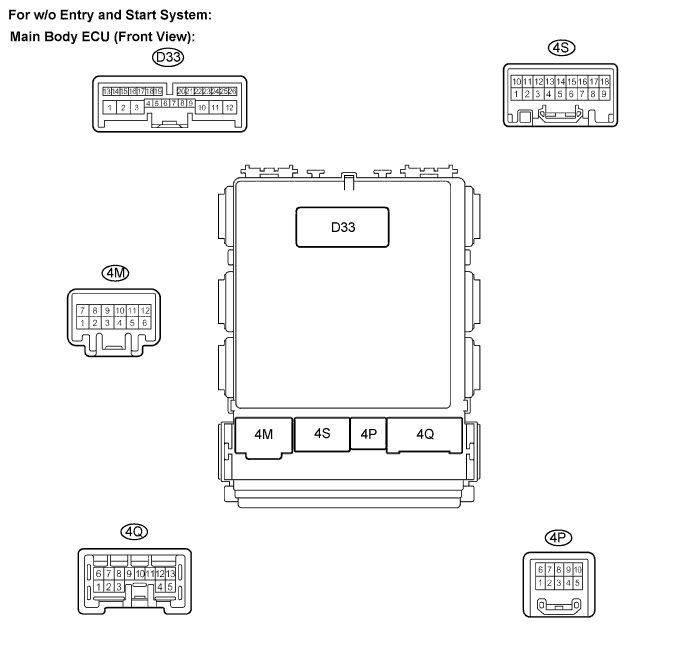
Disconnect the 4B and 4E main body ECU (vehicle rear side) connectors.
Measure the voltages of the wire harness side connectors.
*: w/ Entry and start systemStandard voltage: Symbols (Terminals No.)
Wiring Color
Terminal Description
Condition
Specified Condition
BECU (4B-30) - GND1 (4E-17)
L - W-B
Battery
(Power supply)
Always
10 to 14 V
GND1 (4E-17) - Body ground
W-B - Body ground
Ground
Always
Below 1 V
GND2 (D65-4)* - Body ground
W-B - Body ground
Ground
Always
Below 1 V
If the result is not as specified, there may be a malfunction in the wire harness.Reconnect the main body ECU (vehicle rear side) connectors.
Measure the voltages of the wire harness side connectors.
*1: w/ entry and start systemStandard voltage: Symbols (Terminals No.)
Wiring Color
Terminal Description
Condition
Specified Condition
DCTY (4A-21) - Body ground
L - Body ground
Driver door courtesy switch input
Driver door closed
10 to 14 V
DCTY (4A-21) - Body ground
L - Body ground
Driver door courtesy switch input
Driver door open
0 V
PCTY (4A-24) - Body ground
R - Body ground
Front passenger door courtesy switch input
Passenger door closed
10 to 14 V
PCTY (4A-24) - Body ground
R - Body ground
Front passenger door courtesy switch input
Passenger door open
0 V
RRCY (4A-20)*2 - Body ground
L - Body ground
Rear RH door courtesy switch input
Rear RH door closed
10 to 14 V
RRCY (4A-20)*2 - Body ground
L - Body ground
Rear RH door courtesy switch input
Rear RH door open
0 V
RRCY (4A-5)*2 - Body ground
G - Body ground
Rear LH door courtesy switch input
Rear LH door closed
10 to 14 V
RRCY (4A-5)*2 - Body ground
G - Body ground
Rear LH door courtesy switch input
Rear LH door open
0 V
RRCY (4A-5)*3 - Body ground
Y - Body ground
Rear LH and RH door courtesy switch input
Rear LH and RH doors closed
10 to 14 V
RRCY (4A-5)*3 - Body ground
Y - Body ground
Rear LH and RH door courtesy switch input
Rear LH or RH doors open
0 V
BCTY (4A-7)*4 - Body ground
SB- Body ground
Back door courtesy switch input
Back door closed
10 to 14 V
BCTY (4A-7)*4 - Body ground
SB- Body ground
Back door courtesy switch input
Back door open
0 V
BCTY (4A-7)*3 - Body ground
SB- Body ground
Luggage compartment door courtesy switch input
Luggage compartment door closed
10 to 14 V
BCTY (4A-7)*3 - Body ground
SB- Body ground
Luggage compartment door courtesy switch input
Luggage compartment door open
0 V
SWIL (D65-8)*1 - GND2 (D65-4)*1
LG*1 - W-B*1
Illumination signal (To ignition switch illumination)
Light control switch TAIL or HEAD
10 to 14 V
SWIL (D65-8)*1 - GND2 (D65-4)*1
LG*1 - W-B*1
Illumination signal (To ignition switch illumination)
Light control switch OFF
0 V
*2: 5 Door
*3: Sedan
*4: Hatchback
If the result is not as specified, there may be a malfunction on the wire harness side.