INSTALLATION
Removal / installation · Vehicles built from Jan 2006
| 1. INSTALL REAR BRAKE DRUM SUB-ASSEMBLY |
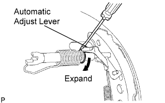
| 2. ADJUST REAR DRUM BRAKE SHOE CLEARANCE |

  |
Provisionally install the 2 hub nuts.
Remove the hole plug, and turn the adjuster to expand the shoe until the drum locks.
Using a screwdriver, release the adjuster 12 notches.
Install the hole plug.
| 3. FILL RESERVOIR WITH BRAKE FLUID |
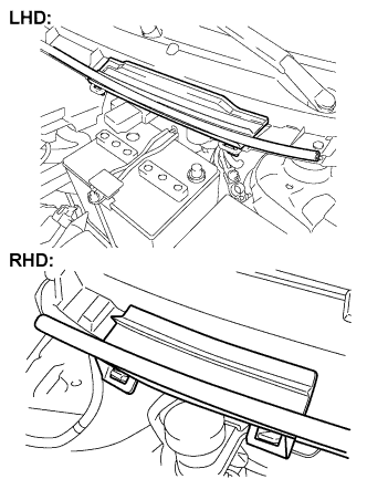 |
Remove the cowl top No. 2 ventilator louver center.
Set the brake fluid can upside down on the reservoir.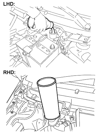
- Fluid:
- SAE J1703 or FMVSS No. 116 DOT3
- SAE J1704 or FMVSS No. 116 DOT4
| 4. BLEED MASTER CYLINDER |
- HINT:
- If the master cylinder has been disassembled or if the reservoir becomes empty, bleed the air from the master cylinder.
Using SST, disconnect the brake tubes from the master cylinder.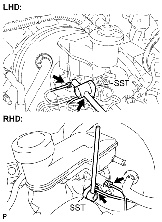
- SST
- 09023-00100
Slowly depress the brake pedal and hold it there (Step A).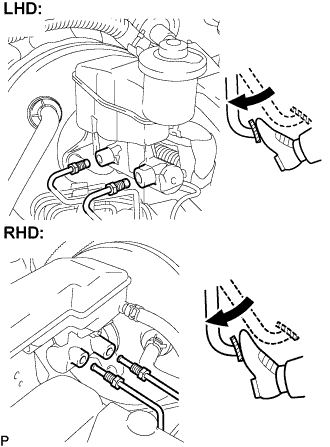
Block the outer holes with your fingers, and release the brake pedal (Step B).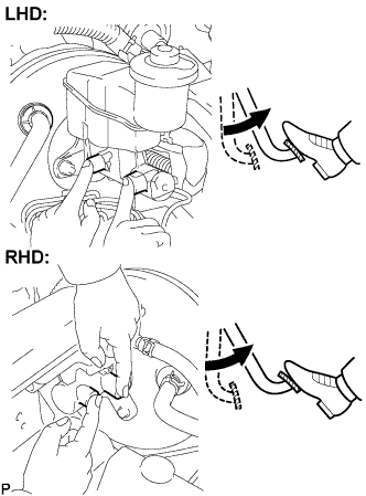
Repeat steps A and B 3 or 4 times.
Using SST, connect the brake tubes to the master cylinder.
- SST
- 09023-00100
- Torque:
- for use without SST:
- 15 N*m{ 155 kgf*cm , 11 ft.*lbf }
- for use with SST:
- 14 N*m{ 143 kgf*cm , 10 ft.*lbf }
- HINT:
- Use a torque wrench with a fulcrum length of 300 mm (11.81 in.).
- This torque value is effective when SST is parallel to a torque wrench.
- Use a torque wrench with a fulcrum length of 300 mm (11.81 in.).
| 5. BLEED BRAKE LINE |
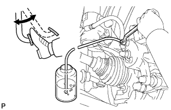 |
Connect the vinyl tube to the bleeder plug.
Depress the brake pedal several times, then loosen the bleeder plug with the pedal depressed (Step C).
At the point where the fluid stops coming out, tighten the bleeder plug, then release the brake pedal (Step D).
Repeat steps C and D until all the air in the fluid is completely bled out.
Tighten the bleeder plug.
- Torque:
- 8.3 N*m{ 85 kgf*cm , 73 in.*lbf }
Repeat the above procedure to bleed the air out of the brake line for each wheel.
| 6. CHECK FLUID LEVEL IN RESERVOIR |
Check the fluid level and add fluid if necessary.
- Fluid:
- SAE J1703 or FMVSS No. 116 DOT3
- SAE J1704 or FMVSS No. 116 DOT4
| 7. CHECK FOR BRAKE FLUID LEAKAGE |
| 8. INSTALL REAR WHEEL |
- Torque:
- 103 N*m{ 1,050 kgf*cm , 76 ft.*lbf }
| 9. INSPECT PARKING BRAKE LEVER TRAVEL |
Slowly pull the parking brake lever to the fully applied position, counting the number of clicks.
- Parking brake lever travel:
- 6 to 9 clicks at 200 N (20 kgf, 45 lbf)
| 10. ADJUST PARKING BRAKE LEVER TRAVEL |
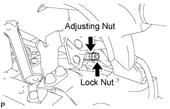 |
Loosen the lock nut and turn the adjusting nut until the parking brake lever travel is corrected to within the specified range.
- Parking brake lever travel:
- 6 to 9 clicks at 200 N (20 kgf, 45 lbf)
Tighten the lock nut.
- Torque:
- 5.4 N*m{ 55 kgf*cm , 48 in.*lbf }
Operate the parking brake lever 3 to 4 times, and check the parking brake lever travel.
Check whether the parking brake drags or not.
When operating the parking brake lever, check that the brake warning light illuminates.
- Standard:
- Brake warning light always illuminates at the first click.