REMOVAL
Removal / installation · Vehicles built from Nov 2006
| 1.
DISCONNECT CABLE FROM NEGATIVE BATTERY TERMINAL |
|
| 2.
DRAIN BRAKE FLUID |
 |
- NOTICE:
- Immediately wash off any brake fluid that comes into contact with any painted surfaces.
| 3.
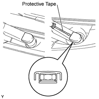
REMOVE FRONT WIPER ARM HEAD CAP
|
|
Using a screwdriver with its tip wrapped in protective tape, disengage the claw and remove the 2 front wiper arm head caps.
| 4.
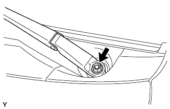
REMOVE FRONT WIPER ARM AND BLADE ASSEMBLY LH
|
|
Operate the wiper, then stop the windshield wiper motor in the automatic stop position.
- Remove the nut and front wiper arm.
| 5.
REMOVE FRONT WIPER ARM AND BLADE ASSEMBLY RH
|
|
- HINT:
- Use the same procedure as for the LH side.
| 6.
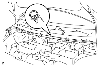
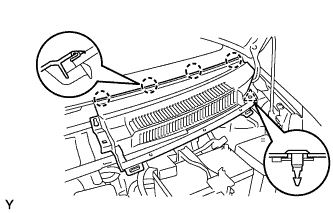
REMOVE HOOD TO COWL TOP SEAL
|
|
Disengage the 7 clips and remove the hood to cowl top seal.
| 7.
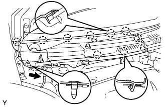
REMOVE COWL TOP VENTILATOR LOUVER SUB-ASSEMBLY
|
|
Disconnect the washer hose.
Disengage the 10 claws and clip and remove the cowl top ventilator louver sub-assembly.
| 8.
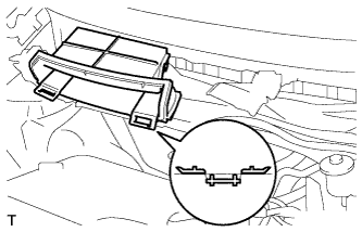
REMOVE COWL TOP VENTILATOR LOUVER LH
|
|
Remove the clip.
Disengage the 4 claws and remove the cowl top ventilator louver LH.
| 9.
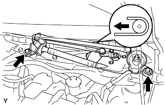
REMOVE FRONT WIPER MOTOR AND LINK
|
|
Remove the 2 bolts.
Slide the wiper link. Disengage the meshing of the rubber pin, then disconnect the connector and remove the front wiper motor and link.
| 10.
REMOVE NO. 2 COWL TO REGISTER DUCT SUB-ASSEMBLY
|
|
Disengage the claw and remove the No. 2 cowl to register duct sub-assembly.
| 11.
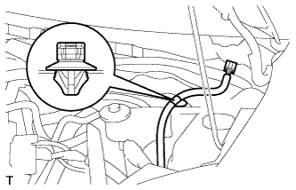
REMOVE OUTER COWL TOP PANEL
|
|
Disengage the wire harness clamp.
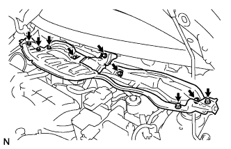
- Remove the 9 bolts and remove the cowl top panel outer.
| 12.
DISCONNECT CLUTCH RESERVOIR TUBE |
|
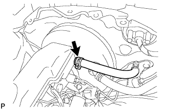
Slide the clip and disconnect the reservoir tube.
| 13.
REMOVE BRAKE MASTER CYLINDER |
|
- NOTICE:
- Remove the brake master cylinder after depressing the brake pedal several times and bleeding the vacuum pressure from inside the brake booster.
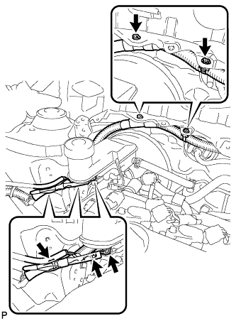
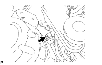
- Disconnect the brake fluid level warning switch connector.
Disconnect the 4 wire harness clamps.
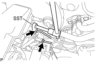
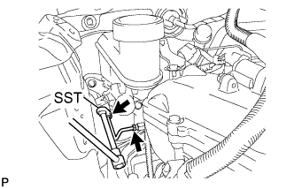
- Using SST, separate the 2 brake tubes from the brake master cylinder.
- SST
- 09023-00100
- Using SST, loosen the 2 brake tubes.
- SST
- 09023-00100
- Loosen the union bolt.
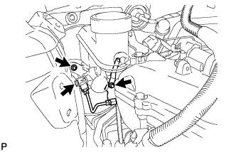
- Remove the 2 nuts.
Remove the vacuum check valve bracket.
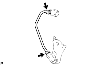
Remove the union bolt, 2 gaskets, union with brake tube and brake tube way.
Remove the brake master cylinder from the brake booster.
Remove the O-ring from the brake master cylinder.
- Remove the brake tube from the union and brake tube way.