REMOVAL
Removal / installation · Vehicles built from Aug 2005
| 1. DISCONNECT CABLE FROM NEGATIVE BATTERY TERMINAL |
| 2. DRAIN BRAKE FLUID |

- NOTICE:
- Immediately wash off any brake fluid that comes into contact with any painted surfaces.
| 3. REMOVE FRONT WIPER ARM HEAD CAP |
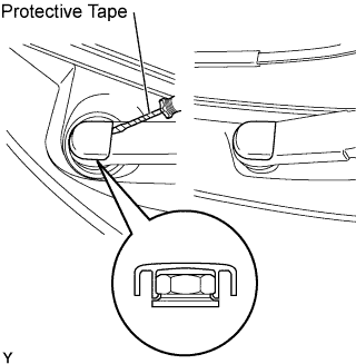  |
Using a screwdriver with its tip wrapped in protective tape, disengage the claw and remove the 2 front wiper arm head caps.
| 4. REMOVE FRONT WIPER ARM AND BLADE ASSEMBLY LH |
- HINT:
- Use the same procedure as for the RH side.
| 5. REMOVE FRONT WIPER ARM AND BLADE ASSEMBLY RH |
Operate the wiper, then stop the windshield wiper motor in the automatic stop position.
Remove the nut and front wiper arm.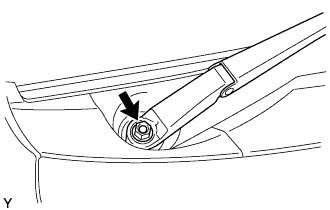
| 6. REMOVE HOOD TO COWL TOP SEAL |
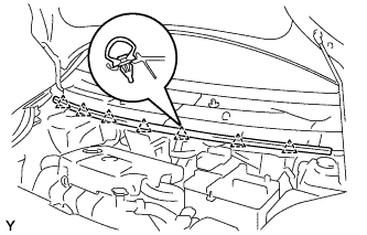 |
Disengage the 7 clips and remove the hood to cowl top seal.
| 7. REMOVE COWL TOP VENTILATOR LOUVER SUB-ASSEMBLY |
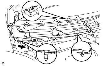 |
Disconnect the washer hose.
Disengage the 10 claws and clip and remove the cowl top ventilator louver sub-assembly.
| 8. REMOVE COWL TOP VENTILATOR LOUVER LH |
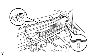 |
Remove the clip.
Disengage the 4 claws and remove the cowl top ventilator louver LH.
| 9. REMOVE FRONT WIPER MOTOR AND LINK |
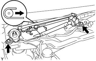 |
Remove the 2 bolts.
Slide the wiper link. Disengage the meshing of the rubber pin, then disconnect the connector and remove the front wiper motor and link.
| 10. REMOVE NO. 2 COWL TO REGISTER DUCT SUB-ASSEMBLY |
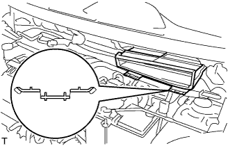 |
Disengage the claw and remove cowl to register duct sub-assembly No. 2.
| 11. REMOVE COWL TOP PANEL OUTER |
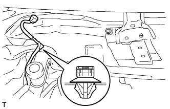 |
Disengage the wire harness clamp.
Remove the 9 bolts and remove the cowl top panel outer.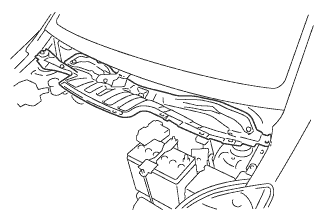
| 12. DISCONNECT CLUTCH RESERVOIR TUBE (for Manual Transaxle) |
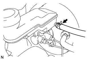 |
Slide the clip and disconnect the reservoir tube.
| 13. REMOVE BRAKE MASTER CYLINDER |
- NOTICE:
- Remove the brake master cylinder after depressing the brake pedal several times and bleeding the vacuum pressure from inside the brake booster.
Disconnect the brake fluid level warning switch connector.
Using SST, separate the 2 brake tubes from the brake master cylinder.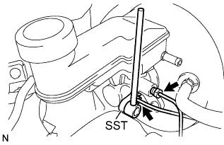
- SST
- 09023-00100
Remove the 2 nuts and remove the brake master cylinder.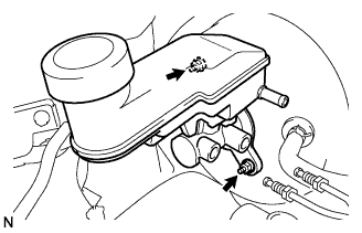
Remove the O-ring from the brake master cylinder.
| 14. REMOVE INSTRUMENT PANEL NO. 1 UNDER COVER SUB-ASSEMBLY (w/ Instrument Panel No. 1 Under Cover Sub-assembly) |
Remove the 2 screws.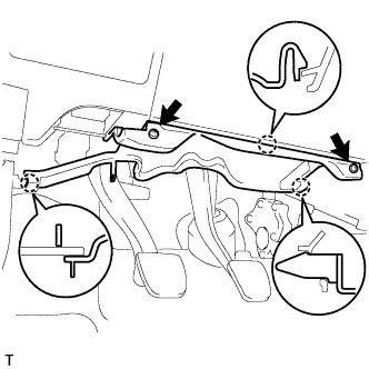
Disengage the 3 claws and remove the instrument panel under cover.
| 15. REMOVE STOP LIGHT SWITCH |
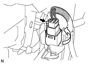 |
Disconnect the connector from the stop light switch.
Turn the stop light switch counterclockwise, and remove the stop light switch.
| 16. REMOVE STOP LIGHT SWITCH MOUNTING ADJUSTER |
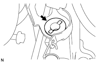 |
Remove the stop light switch mounting adjuster from the pedal support.
| 17. REMOVE BRAKE MASTER CYLINDER PUSH ROD CLEVIS |
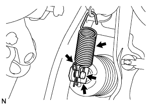 |
Remove the brake pedal return spring.
Loosen the push rod lock nut.
Remove the clip and the push rod pin and separate the push rod clevis from the brake pedal.
Remove the push rod clevis from the brake booster.
| 18. REMOVE BRAKE BOOSTER |
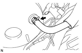 |
Slide the clip and disconnect the vacuum hose from the check valve.
Remove the bolt and separate the wire harness bracket.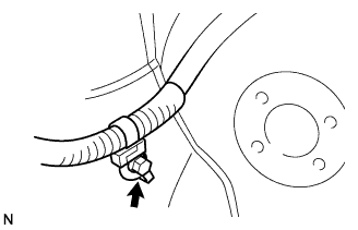
Remove the wire harness clamp and 4 nuts and remove the brake booster.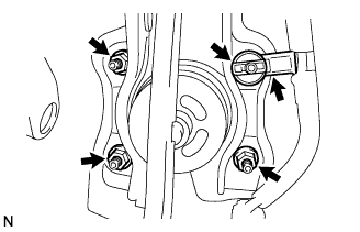
Remove the gasket from the brake booster.
| 19. REMOVE BRAKE VACUUM CHECK VALVE ASSEMBLY |
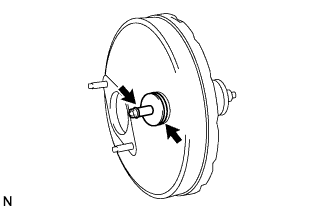 |
Remove the vacuum check valve from the brake booster.
Remove the grommet from the brake booster.