Steering Pad Switch Circuit
Circuit diagnosis · Vehicles built from Aug 2005
DESCRIPTION
This circuit sends signals from the steering pad switch to the radio receiver.WIRING DIAGRAM
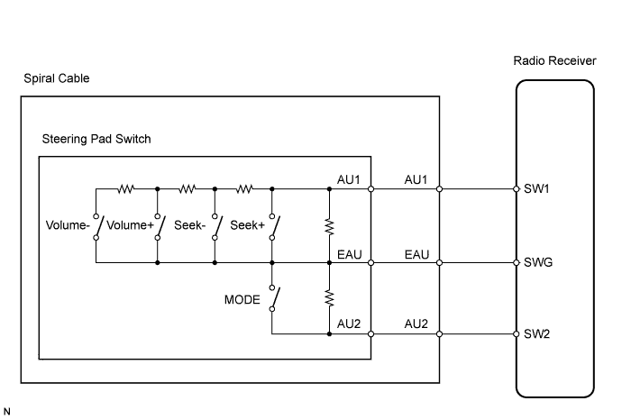

INSPECTION PROCEDURE
| 1. INSPECT STEERING PAD SWITCH |

Inspect the steering pad switch (Click here).
- OK:
- Steering pad switch is normal.
|
|
||||

| OK | |
 |
| 2. CHECK HARNESS AND CONNECTOR (RADIO RECEIVER - SPIRAL CABLE) |
Disconnect the D53 radio receiver connector.
Disconnect the D3 spiral cable connector.
Measure the resistance.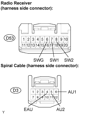
- Standard Resistance:
Tester Connection
Specified Condition
D53-7 (SW1) - D3-6 (AU1)
Below 1 Ω
D53-8 (SW2) - D3-5 (AU2)
Below 1 Ω
D53-6 (SWG) - D3-4 (EAU)
Below 1 Ω
D53-7 (SW1) - Body ground
10 kΩ or higher
D53-8 (SW2) - Body ground
10 kΩ or higher
D53-6 (SWG) - Body ground
10 kΩ or higher
|
|
||||
| OK | |
|
| 3. INSPECT SPIRAL CABLE |
Disconnect the spiral cable connector.
Measure the resistance.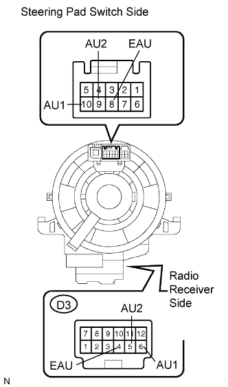
- Standard Resistance:
Tester Connection
Specified Condition
D3-4 (EAU) - 8 (EAU)
Below 1 Ω
D3-6 (AU1) - 10 (AU1)
Below 1 Ω
D3-5 (AU2) - 9 (AU2)
Below 1 Ω
|
|
||||
| OK | ||
 |
||
| ||