REMOVAL
Removal / installation · Vehicles built from Nov 2005
| 1. DISCONNECT CABLE FROM NEGATIVE BATTERY TERMINAL |
| 2. REMOVE FRONT WIPER ARM HEAD CAP |

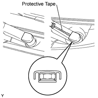  |
Using a screwdriver with its tip wrapped in protective tape, disengage the claw and remove the 2 front wiper arm head caps.
| 3. REMOVE FRONT WIPER ARM AND BLADE ASSEMBLY LH |
Operate the wiper, then stop the windshield wiper motor in the automatic stop position.
Remove the nut and front wiper arm.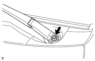
| 4. REMOVE FRONT WIPER ARM AND BLADE ASSEMBLY RH |
- HINT:
- Use the same procedure as for the LH side.
| 5. REMOVE HOOD TO COWL TOP SEAL |
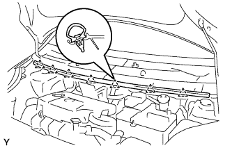 |
Disengage the 7 clips and remove the hood to cowl top seal.
| 6. REMOVE COWL TOP VENTILATOR LOUVER SUB-ASSEMBLY (for LHD) |
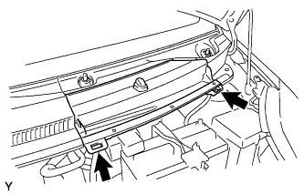 |
Disengage the 2 hooks and remove cowl top ventilator louver center No. 1.
Disconnect the washer hose.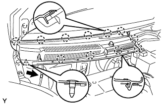
Disengage the 11 claws and clip.
Disconnect the washer hose and remove the cowl top ventilator louver sub-assembly.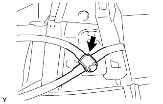
| 7. REMOVE COWL TOP VENTILATOR LOUVER SUB-ASSEMBLY LH (for LHD) |
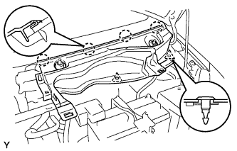 |
Remove the 2 clips.
Disengage the 4 claws and remove the cowl top ventilator louver LH.
| 8. REMOVE COWL TOP VENTILATOR LOUVER SUB-ASSEMBLY (for RHD) |
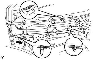 |
Disconnect the washer hose.
Disengage the 10 claws and clip and remove the cowl top ventilator louver sub-assembly.
| 9. REMOVE COWL TOP VENTILATOR LOUVER LH (for RHD) |
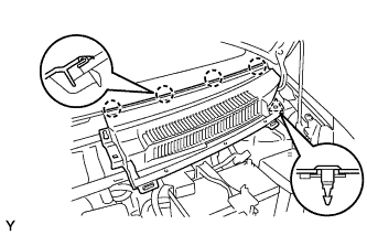 |
Remove the clip.
Disengage the 4 claws and remove the cowl top ventilator louver LH.
| 10. REMOVE FRONT WIPER MOTOR AND LINK ASSEMBLY |
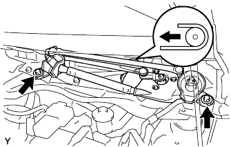 |
Remove the 2 bolts.
Slide the wiper link. Disengage the meshing of the rubber pin, then disconnect the connector and remove the front wiper motor and link.
| 11. REMOVE COWL TO REGISTER DUCT SUB-ASSEMBLY NO. 2 |
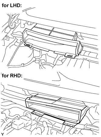 |
Disengage the claws, and remove cowl top register duct No. 2.
| 12. REMOVE COWL TOP PANEL OUTER |
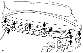 |
Separate the wire harness.
Remove the 9 bolts and cowl top panel outer.
| 13. REMOVE FUEL FILTER ASSEMBLY |
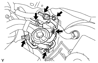 |
Disconnect the 4 fuel hoses from the fuel filter.
Disconnect the connector.
Remove the bolt, then remove the fuel filter.
| 14. DRAIN FUEL |
Loosen the drain plug, then drain the fuel from the fuel filter.
| 15. REMOVE LEVEL WARNING SWITCH |
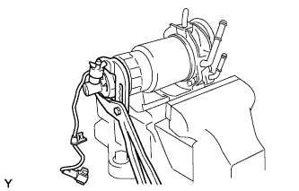 |
Clamp the fuel filter in a soft jaw vise.
Using pliers, remove the level warning switch.
- NOTICE:
- Do not damage the level warning switch.
| 16. REMOVE FUEL FILTER ELEMENT |
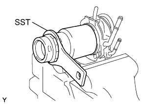 |
Using SST, remove the fuel filter element.
- SST
- 09228-64030