Removal / installation · Vehicles built from Nov 2005
1.
DISCONNECT CABLE FROM NEGATIVE BATTERY TERMINAL
2.
REMOVE FRONT WHEEL RH
3.
DRAIN ENGINE COOLANT
CAUTION:
To avoid the danger of being burned, do not remove the radiator cap while the engine and radiator are still hot. Thermal expansion will cause hot engine coolant and steam to blow out from the radiator.
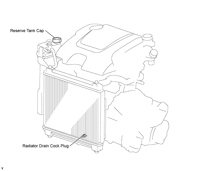
Loosen the radiator drain cock plug.
Remove the reserve tank cap and drain the coolant.
Tighten the radiator drain cock plug.
4.
REMOVE ENGINE UNDER COVER
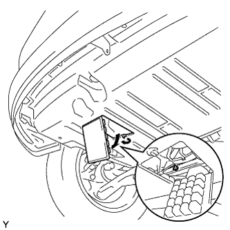
Remove the 5 bolts, 4 screws and 2 clips and remove the engine under cover.
5.
REMOVE ENGINE COVER SUB-ASSEMBLY NO. 1
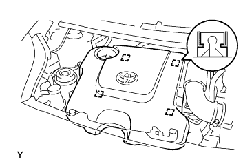
Disengage the 4 pins and remove engine cover No. 1.
6.
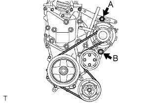
REMOVE FAN AND GENERATOR V BELT
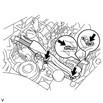
Remove the 3 bolts and clip, then separate the wire harness.
Loosen bolts A and B.
Remove the fan and generator V belt.
7.
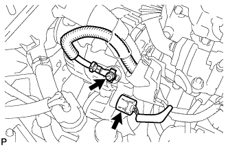
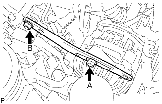
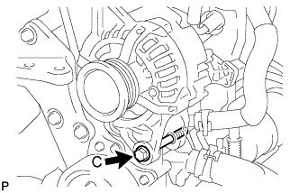
REMOVE GENERATOR ASSEMBLY
Remove the terminal cap.
Separate the connector and harness clamp.
Remove the nut and remove terminal B.
Remove fan belt adjusting slider fixing bolt A and nut B and remove the fan belt adjusting slider.
Remove fixing bolt C and remove the generator.
8.
REMOVE WATER PUMP PULLEY
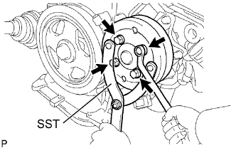
Using SST, hold the water pump pulley.
SST
09960-10010
(09962-01000, 09963-00700)
Remove the 4 bolts, then remove the water pump pulley.
9.
REMOVE WATER PUMP ASSEMBLY
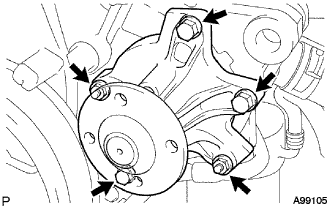
Remove the 3 bolts and 2 nuts, then remove the water pump.
10.
REMOVE CYLINDER HEAD COVER SUB-ASSEMBLY
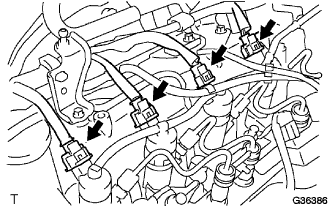
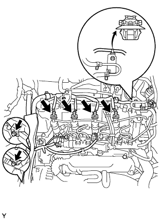
Disconnect the injector connectors.
Disconnect the supply pump connector.
Disengage the wire harness clamps shown in the illustration.
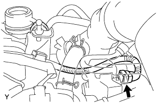
Disconnect the VSV connector shown in the illustration, and disengage the wire harness clamp shown in the illustration.
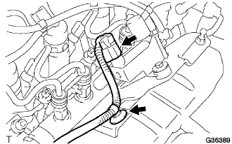
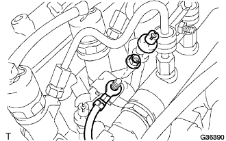
Remove the screw grommet and nut, then separate the wire harness.
Disconnect the common rail connector.
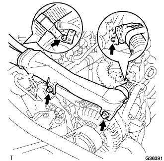
Remove the 3 bolts and the wire harness clamp shown in the illustration and disconnect the engine wire harness.
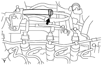
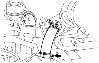
Disconnect the hose shown in the illustration.
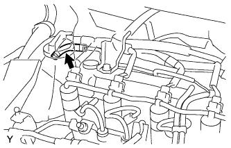
Disconnect the hose shown in the illustration.
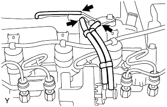
Disconnect the 3 vacuum hoses shown in the illustration.
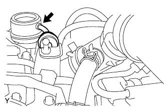
Disconnect the vacuum hose shown in the illustration.
Disconnect the ventilation hose from the cylinder head.
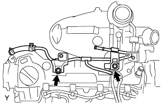
Remove the 2 bolts, then remove the connector to vacuum reservoir tube.
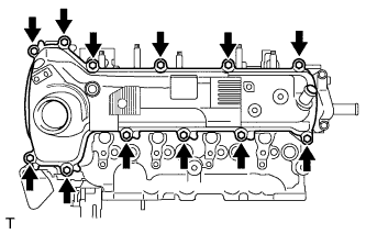
Remove the 12 bolts, then remove the cylinder head cover.
11.
REMOVE VACUUM PUMP ASSEMBLY
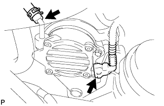
Slide the clip and disconnect the vacuum hose.
Disconnect the cam position sensor connector.
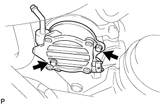
Remove the 2 bolts and vacuum pump.
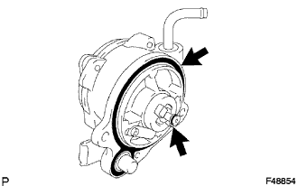
Remove the 2 O-rings from the vacuum pump.
12.
REMOVE CRANKSHAFT DAMPER SUB-ASSEMBLY
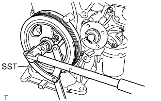
Using SST, hold the crankshaft damper and loosen the crankshaft bolt.