INSTALLATION
Removal / installation · Vehicles built from Nov 2005
| 1. INSTALL THERMOSTAT |

Install a new gasket onto the thermostat.
Install the thermostat with the jiggle valve upward.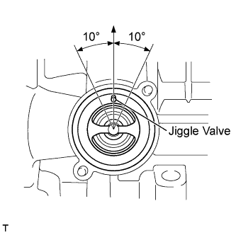

- HINT:
- The jiggle valve may be set to within 10° on either side of the prescribed position.
| 2. INSTALL WATER INLET |
Install the water inlet with the 2 nuts.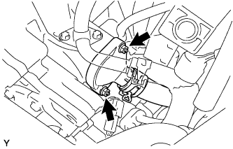
- Torque:
- 9.0 N*m{ 92 kgf*cm , 80 in.*lbf }
| 3. INSTALL FAN BELT ADJUSTING BAR |
Install the fan belt adjusting bar with nut.
| 4. INSTALL GENERATOR ASSEMBLY |
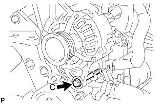 |
Provisionally install the generator with fixing bolt C.
Provisionally install the fan belt adjusting slider with fan belt adjusting slider fixing bolt A and nut B, then move the generator toward the cylinder block and tighten bolt B.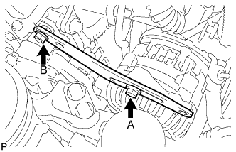
- Torque:
- 19 N*m{ 189 kgf*cm , 14 ft.*lbf } for Bolt B
Install the connector.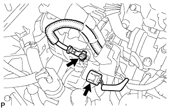
Install terminal B with the nut.
- Torque:
- 9.8 N*m{ 100 kgf*cm , 87 in.*lbf }
Install the terminal cap.
| 5. INSTALL FAN AND GENERATOR V BELT |
Temporarily install the fan and generator V belt onto each pulley.
- NOTICE:
- Before installing the V belt, check each pulley for any kind of liquid and chips.
- Before installing the V belt, check each pulley for any kind of liquid and chips.
- Check that the ribs of the V belt are correctly fitted into the grooves of the pulleys.
- Check that the ribs of the V belt are correctly fitted into the grooves of the pulleys.
| 6. ADJUST FAN AND GENERATOR V BELT |
Insert a bar between the generator and the engine. Pull the bar toward the front of the vehicle and adjust the tension.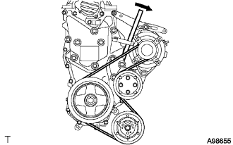
Tighten bolt A, then tighten bolt B.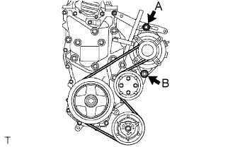
- Torque:
- Bolt A:
- 19 N*m{ 189 kgf*cm , 14 ft.*lbf }
- Bolt B:
- 32 N*m{ 326 kgf*cm , 24 ft.*lbf }
| 7. INSPECT FAN AND GENERATOR V BELT |
Inspect the fan and generator V belt deflection.
- Pressing force:
- 98 N (10kgf, 221 lbf)
New belt
mm (in.)
Used belt
mm (in.)
5.0 to 6.0
(0.197 to 0.236)
7.0 to 8.5
(0.276 to 0.335)
Inspection the fan and generator V belt tension.
New belt
mm (in.)
Used belt
mm (in.)
980 to 1176
(100 to 120, 220 to 264)
490 to 686
(50 to 70, 110 to 154)
- NOTICE:
- Check the V belt deflection at the specified point.
- Check the V belt deflection at the specified point.
- When installing a new belt, set its tension value as specified.
- When installing a new belt, set its tension value as specified.
- When checking a belt used for over 5 minutes, confirm that the deflection value is within the specified range for a used belt.
- When checking a belt used for over 5 minutes, confirm that the deflection value is within the specified range for a used belt.
- When reinstalling a belt used for over 5 minutes, check whether its deflection value is within the specified range for the used belt.
- When reinstalling a belt used for over 5 minutes, check whether its deflection value is within the specified range for the used belt.
- When using a belt tension gauge, confirm its accuracy first by using a master gauge.
- When using a belt tension gauge, confirm its accuracy first by using a master gauge.
| 8. CONNECT CABLE TO NEGATIVE BATTERY TERMINAL |
- Torque:
- 5.4 N*m{ 55 kgf*cm , 48 in.*lbf }
| 9. ADD ENGINE COOLANT |
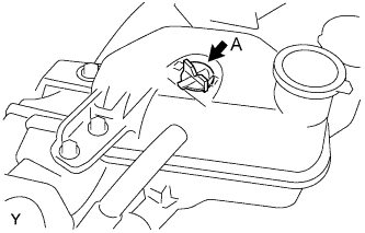 |
Remove air bleed valve A.
Fill the cooling system with coolant up to line B.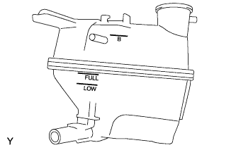
- Capacity:
- 4.7 liters (5.0 US qts, 4.1 lmp. qts)
- HINT:
- Use of improper coolant may damage the engine cooling system.
- Use only Toyota Super Long Life Coolant or similar high quality ethylene glycol based non-silicate, non-amine, non-nitrite, and non-borate engine coolant with long-life hybrid organic acid technology (coolant with long-life hybrid organic acid technology consists of a combination of low phosphates and organic acids).
- Use of improper coolant may damage the engine cooling system.
- NOTICE:
- Do not substitute plain water for engine coolant.
Tighten air bleed valve A.
Install the radiator cap.
Warm up the engine.
Set the air conditioning as follows while warming up the engine.
Item
Manual air conditioning system
Automatic air conditioning system
Set control as follows
Fan speed - Any setting except "OFF"
Temperature - Toward WARM
Air conditioning switch "OFF"
Fan speed - Any setting except "OFF"
Temperature - To the highest temperature
Air conditioning switch "OFF"
"AUTO" switch "OFF"
Run the engine at 3,000 rpm for 5 seconds and idling for 45 seconds alternately.
Do the above operation for 7 minutes or more.
After the engine cools down, check that the coolant level is between LOW and FULL lines.
| 10. CHECK ENGINE COOLANT LEAK |
- CAUTION:
- To avoid the danger of being burned, do not remove the radiator cap sub-assembly while the engine and radiator assembly are still hot. Thermal expansion will cause hot engine coolant and steam to blow out from the radiator assembly.
Fill the radiator assembly with engine coolant, then attach a radiator cap tester.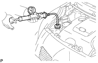
Pump it to 137 kPa (1.4 kgf/cm2, 19.9 psi), then check that the pressure does not drop.
If the pressure drops, check the hoses, radiator assembly and water pump assembly for leakage. If there are no signs or traces of external engine coolant leakage, check the heater core, cylinder block and head.
| 11. INSTALL ENGINE UNDER COVER |
Provisionally install the engine under cover with the 5 bolts, 4 screws and 2 clips.
Tighten the 4 screws.
Tighten the 5 bolts.
- Torque:
- 5.0 N*m{ 51 kgf*cm , 44 in.*lbf }
| 12. INSTALL ENGINE COVER SUB-ASSEMBLY NO. 1 |
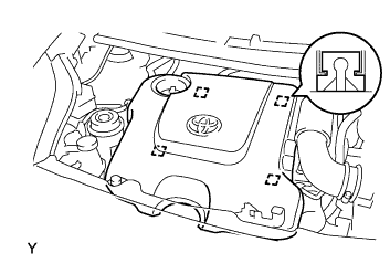 |
Engage the 4 pins and install engine cover No. 1.