INSTALLATION
Removal / installation · Vehicles built from Nov 2005
| 1. INSTALL KNOCK SENSOR |

Install the knock sensor, in the direction shown in the illustration with the nut.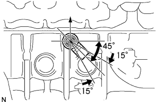

- Torque:
- 11 N*m{ 112 kgf*cm , 8 ft.*lbf }
Connect the knock sensor connector.
| 2. INSTALL INTAKE MANIFOLD |
Install a new intake manifold gasket.
Provisionally install the intake manifold with the 3 bolts and 2 nuts.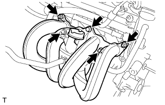
Tighten the 3 bolts and 2 nuts in the sequence order shown in the illustration.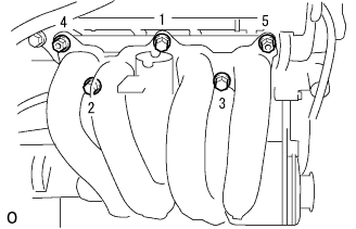
- Torque:
- 25 N*m{ 255 kgf*cm , 18 ft.*lbf }
| 3. INSTALL THROTTLE BODY BRACKET |
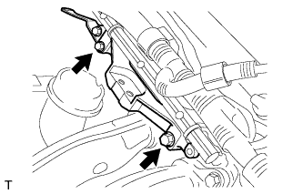 |
Install the throttle body bracket with the 2 bolts.
- Torque:
- 21 N*m{ 214 kgf*cm , 16 ft.*lbf }
| 4. CONNECT ENGINE WIRE HARNESS (for RHD) |
Engage the engine wire harness clamp.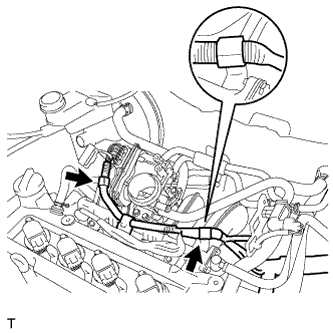
| 5. CONNECT ENGINE WIRE HARNESS (for LHD) |
Install the engine wire harness bracket with the bolt.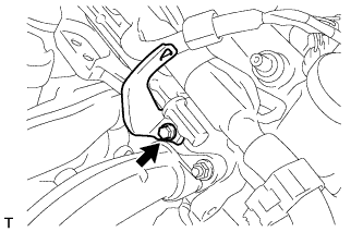
- Torque:
- 13 N*m{ 133 kgf*cm , 10 ft.*lbf }
Connect the 2 engine wire harness clamps.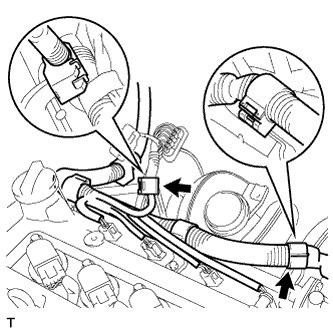
| 6. CONNECT VENTILATION HOSE (for RHD) |
Install the engine wire harness bracket with the bolt.
- Torque:
- 13 N*m{ 133 kgf*cm , 10 ft.*lbf }
Connect the ventilation hose to the cylinder head.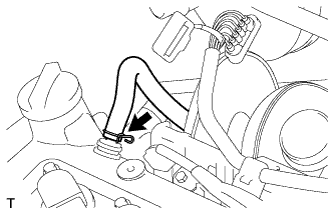
| 7. CONNECT VENTILATION HOSE (for LHD) |
Connect the ventilation hose to the cylinder head.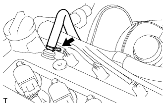
| 8. CONNECT UNION TO CONNECTOR TUBE HOSE (for RHD) |
Connect the union to connector tube hose.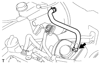
| 9. CONNECT UNION TO CONNECTOR TUBE HOSE (for LHD) |
Connect the union to connector tube hose.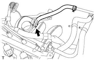
| 10. INSTALL THROTTLE BODY ASSEMBLY |
Install a new O-ring.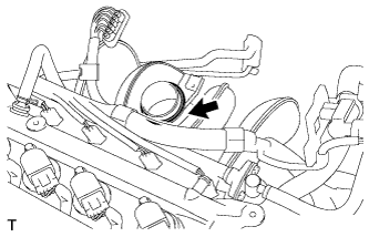
Install the throttle body assembly with the 3 bolts.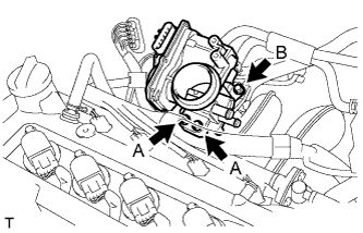
- Torque:
- 21 N*m{ 214 kgf*cm , 16 ft.*lbf } for bolt A
- 9.5 N*m{ 97 kgf*cm , 84 in.*lbf } for bolt B
Connect the connector to the throttle body assembly.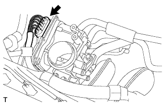
| 11. CONNECT CHARCOAL CANISTER FUEL HOSE |
Connect the charcoal canister fuel hose to the throttle body assembly.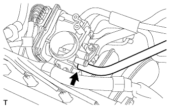
| 12. CONNECT NO. 2 VENTILATION HOSE |
Connect the No. 2 ventilation hose to the throttle body assembly.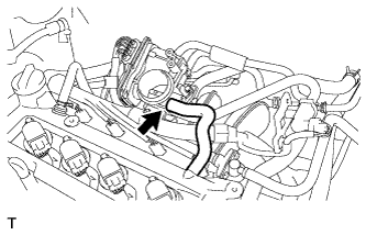
| 13. CONNECT NO. 1 WATER BY-PASS HOSE |
Connect the 2 No. 1 water by-pass hoses.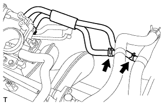
| 14. CONNECT CABLE TO NEGATIVE BATTERY TERMINAL |
- Torque:
- 5.4 N*m{ 55 kgf*cm , 48 ft.*lbf }
| 15. ADD ENGINE COOLANT |
Tighten all the plugs.
Disconnect the vinyl hose.
Pour engine coolant into the radiator assembly until it overflows.
- Capacity:
- 5.1 liters (5.4 USqts, 4.5 lmp. qts)
- NOTICE:
- Do not substitute plain water for engine coolant.
- HINT:
- Use of improper engine coolant may damage the engine coolant system.
- Use only Toyota Super Long Life Coolant or similar high quality ethylene glycol based non-silicate, non-amine, non-nitrite, and non-borate engine coolant with long-life hybrid organic acid technology (coolant with long-life hybrid organic acid technology consists of a combination of low phosphates and organic acids).
- Use of improper engine coolant may damage the engine coolant system.
Check the engine coolant level inside the radiator assembly by squeezing the inlet and outlet radiator hoses several times by hand. If the engine coolant level goes down, add engine coolant.
Install the radiator cap sub-assembly securely.
Slowly pour engine coolant into the radiator reservoir until it reaches the FULL line.
Warm up the engine until the cooling fan operates.
Set the air conditioning as follows while warming up the engine.
Item
Manual air conditioning system
Automatic air conditioning system
Set control as follows
Fan speed - Any setting except "OFF"
Temperature - Toward WARM
Air conditioning switch "OFF"
Fan speed - Any setting except "OFF"
Temperature - To the highest temperature
Air conditioning switch "OFF"
"AUTO" switch "OFF"
Maintain the engine speed at 2,000 to 2,500 rpm and warm up the engine until the cooling fan operates.
Stop the engine and wait until the coolant cools down.
If the engine coolant level is below the full level, perform steps (c) through (h) again and repeat the operation until the engine coolant level stays at the full level.
Recheck the engine coolant level inside the radiator reservoir tank assembly. If it is below the full level, add engine coolant.
| 16. CHECK FOR ENGINE COOLANT LEAK |
- CAUTION:
- To avoid the danger of being burned, do not remove the radiator cap sub-assembly while the engine and radiator assembly are still hot. Thermal expansion will cause hot engine coolant and steam to blow out from the radiator assembly.
Fill the radiator assembly with engine coolant, then attach a radiator cap tester.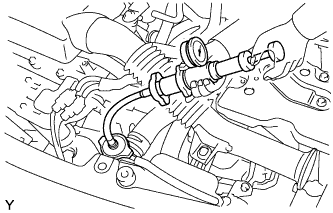
Pump it to 137 kPa (1.4 kgf/cm2, 19.9 psi), then check that the pressure does not drop.
If the pressure drops, check the hoses, radiator assembly and water pump assembly for leakage. If there are no signs or traces of external engine coolant leakage, check the heater core, cylinder block and head.
| 17. INSTALL AIR CLEANER CASE SUB-ASSEMBLY |
Install a new O-ring.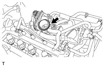
Install the air cleaner case sub-assembly with the 3 bolts.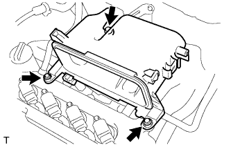
- Torque:
- 7.5 N*m{ 76 kgf*cm , 66 in.*lbf }
Connect the connector to the mass air flow meter.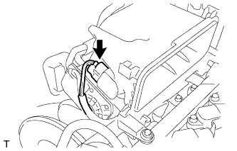
| 18. INSTALL PURGE VSV ASSEMBLY |
Install the bolt and install the purge VSV assembly.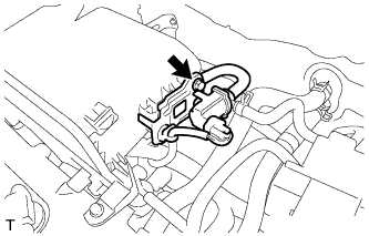
- Torque:
- 8.0 N*m{ 82 kgf*cm , 71 in.*lbf }
| 19. INSTALL AIR CLEANER FILTER ELEMENT SUB-ASSEMBLY |
| 20. INSTALL AIR CLEANER CAP SUB-ASSEMBLY |
Install the air cleaner cap with the grommet and 2 clamps.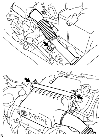
| 21. INSTALL COWL TOP PANEL OUTER |
Install the cowl top panel outer with the 9 bolts.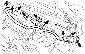
- Torque:
- 6.5 N*m{ 66 kgf*cm , 58 in.*lbf }
Engage the clamp and install the wiper motor connector wire harness.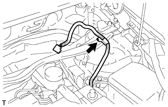
| 22. INSTALL NO. 2 COWL TO REGISTER DUCT SUB-ASSEMBLY |
Engage the 2 claws and install cowl to register duct No. 2.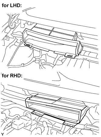
| 23. INSTALL FRONT WIPER MOTOR AND LINK |
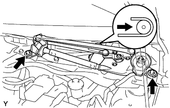 |
Connect the connector.
Slide the wiper link as shown in the illustration and engage the rubber pin with the body.
Install the front wiper motor and link with the 2 bolts.
- Torque:
- 5.5 N*m{ 56 kgf*cm , 49 in.*lbf }
| 24. INSTALL COWL TOP VENTILATOR LOUVER LH (for RHD) |
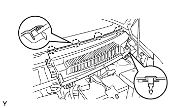 |
Engage the 4 claws and install the cowl top ventilator louver LH.
Install the clip.
| 25. INSTALL COWL TOP VENTILATOR LOUVER SUB-ASSEMBLY (for RHD) |
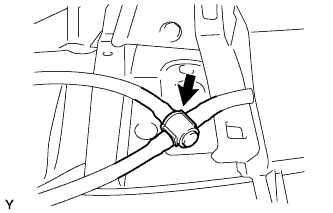 |
Connect the washer hose.
Engage the 11 claws and install the cowl top ventilator louver sub-assembly.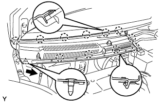
Install the clip.
Connect the washer hose.
Engage the 2 hooks and install cowl top ventilator louver center No. 1.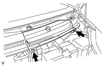
| 26. INSTALL COWL TOP VENTILATOR LOUVER LH (for LHD) |
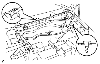 |
Engage the 4 claws and install the cowl top ventilator louver LH.
Install the 2 clips.
| 27. INSTALL COWL TOP VENTILATOR LOUVER SUB-ASSEMBLY (for LHD) |
|
|
Connect the washer hose.
Engage the 11 claws and install the cowl top ventilator louver sub-assembly.
Install the clip.
Connect the washer hose.
Engage the 2 hooks and install cowl top ventilator louver center No. 1.
| 28. INSTALL HOOD TO COWL TOP SEAL |
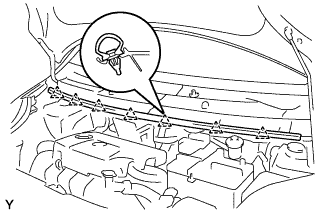 |
Engage the 7 clips and install the hood to cowl top seal.
| 29. INSTALL FR WIPER ARM RH |
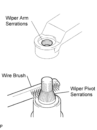 |
Scrape any metal powder off the serrated part of the wiper arm with a round file or the equivalent (when reinstalling).
Clean the wiper pivot serrations with a wire brush.
Operate the wiper, then stop the windshield wiper motor in the automatic stop position.
Align the blade tip with the mark on the windshield glass, as shown in the illustration.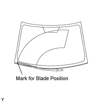
Tighten the nut of the front wiper arm.
- Torque:
- 26 N*m{ 265 kgf*cm , 19 ft.*lbf }
| 30. INSTALL FR WIPER ARM LH |
|
|
Scrape any metal powder off the serrated part of the wiper arm with a round file or the equivalent (when reinstalling).
Clean the wiper pivot serrations with a wire brush.
Operate the wiper, then stop the windshield wiper motor in the automatic stop position.
Align the blade tip with the mark on the windshield glass, as shown in the illustration.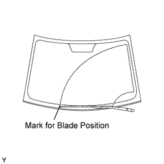
Tighten the nut of the front wiper arm.
- Torque:
- 26 N*m{ 265 kgf*cm , 19 ft.*lbf }
| 31. INSTALL FRONT WIPER ARM HEAD CAP |
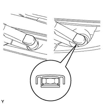 |
Engage the claw and install the 2 front wiper arm head caps.