Removal / installation · Vehicles built from Nov 2005
1.
INSTALL CAMSHAFT SUB-ASSEMBLY
Apply new engine oil to the valve lifter and journal of the cylinder head.
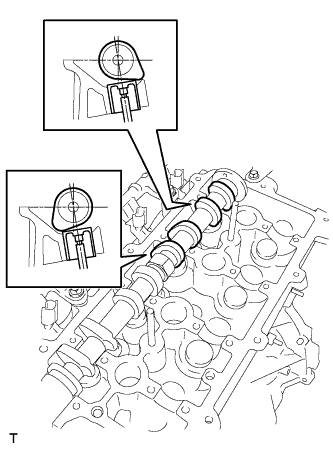
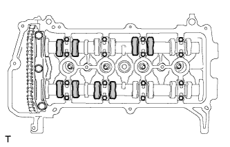
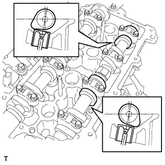
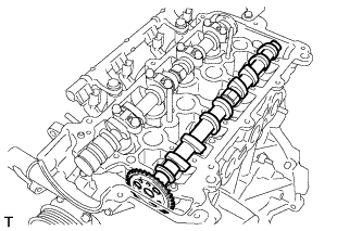
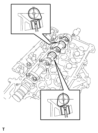
Place the intake camshaft on the cylinder head so that the cam noses of cylinders No. 3 and No. 4 face as shown in the illustration.
Apply new engine oil to the lifter and journal of the cylinder head.
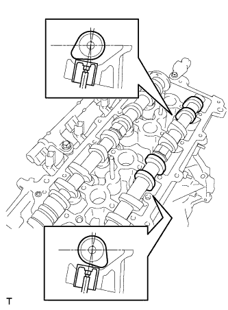
Place the exhaust camshaft on the cylinder head so that the cam noses of cylinders No. 2 and No. 4 face as shown in the illustration.
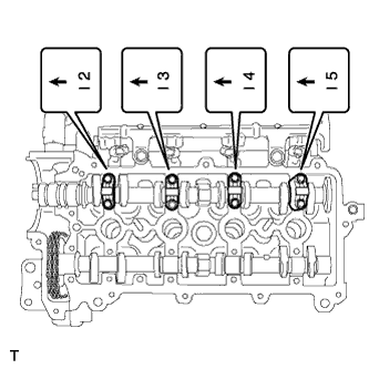
Install the intake camshaft bearing caps with 8 bolts.
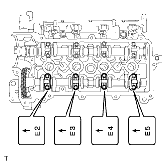
Install the exhaust camshaft bearing caps with 8 bolts.
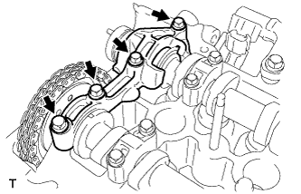
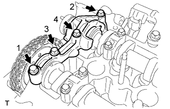
Provisionally install the camshaft bearing cap and 4 bolts as shown in the illustration.
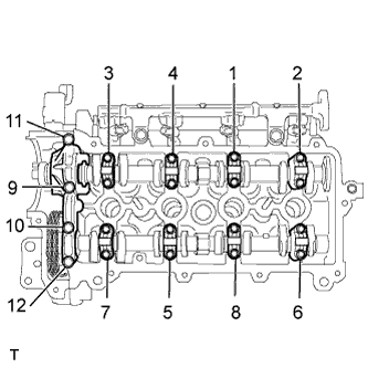
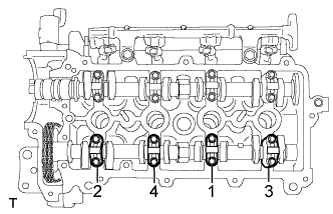
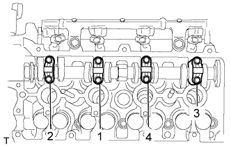
Uniformly tighten the 20 bolts in the sequence shown in the illustration
Torque:
13 N*m{
127 kgf*cm
, 9 ft.*lbf
}
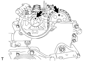
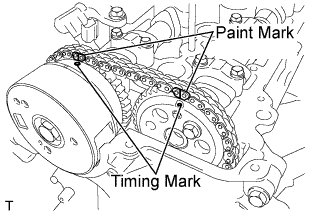
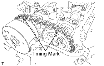
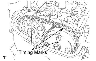
Make sure that the timing marks of the camshaft timing sprocket and the camshaft timing gear are in the positions shown in the illustration.
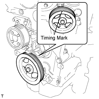
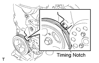
Make sure that the timing mark (cutout) of the crankshaft pulley is in the position shown in the illustration.
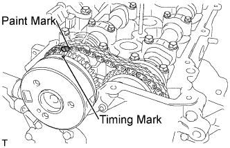
Align the marks of the camshaft timing sprocket and the chain and install them.
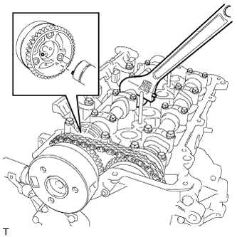
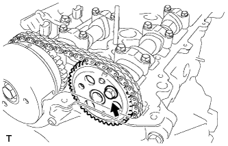
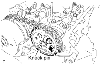
Align the knock pin of the camshaft with the pin hole in the camshaft timing sprocket and install the camshaft timing sprocket onto the camshaft.
NOTICE:
If the knock pin and the pin hole are not aligned, using the hexagonal portion of the camshaft, turn the camshaft slightly both ways and align them. Do not apply excessive force to the camshaft timing sprocket during the alignment, otherwise, the tip of the knock pin could damage the seal surface.
If the knock pin and the pin hole are not aligned, using the hexagonal portion of the camshaft, turn the camshaft slightly both ways and align them. Do not apply excessive force to the camshaft timing sprocket during the alignment, otherwise, the tip of the knock pin could damage the seal surface.
Apply a small amount of engine oil to the screw and seat surface of the camshaft timing sprocket fixing bolt.
Using the hexagonal portion of the camshaft, install the camshaft timing sprocket.
Torque:
47 N*m{
480 kgf*cm
, 35 ft.*lbf
}
Align the marks of the camshaft timing gear or sprocket and the chain and install them.
Align the knock pin of camshaft No. 2 with the pin hole in the camshaft timing gear and install the camshaft timing gear onto camshaft No.2.
HINT:
If the knock pin and the pin hole are not aligned, using the hexagonal portion of the camshaft, turn the camshaft slightly both ways and align them.
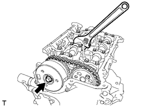
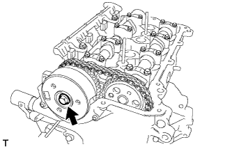
Provisionally tighten the bolt of camshaft No. 2 indicated by the arrow in the illustration.
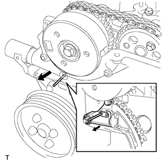
Remove the 3mm diameter bar from the chain tensioner.
NOTICE:
Using the hexagonal portion of the camshaft, turn the camshaft slightly both ways and, with the chain on the tensioner loose, remove the 3mm diameter bar.
Make sure that the crankshaft pulley is in the position shown in the illustration.
Make sure that the timing marks of the camshaft timing sprocket and the camshaft timing gear are in the positions shown in the illustration.
Apply adhesive to the 2 or 3 threads at the tip of the bolt of the chain cover service hole screw plug.
NOTICE:
Keep the bolt and bolt hole free of foreign matter and oil.
Using a socket hexagon wrench 10, install the chain cover service hole screw plug.
Torque:
17 N*m{
173 kgf*cm
, 13 ft.*lbf
}
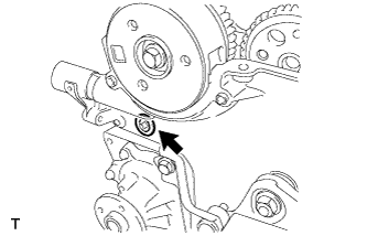
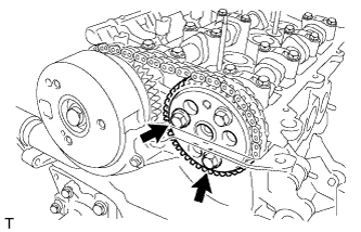
Turn the crankshaft pulley clockwise and install the camshaft timing gear or sprocket with the 3 fixing bolts.
Torque:
8.0 N*m{
82 kgf*cm
, 71 in.*lbf
}
2.
INSPECT VALVE CLEARANCE
HINT:
Inspect the valve clearance when the engine is cold.
Set No.1 cylinder to TDC/compression.
Turn the crankshaft damper and align its timing notch with the timing mark "0" of the oil pump.
for Unleaded Gasoline Specification Vehicle: Check that both timing marks on the camshaft timing sprocket and camshaft timing gear are facing upward, as shown in the illustration.
HINT:
If not, turn the crankshaft 1 complete revolution (360°) and align the marks as above.
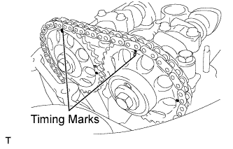
for Leaded Gasoline Specification Vehicle: Check that both timing marks on the camshaft timing sprockets facing upward as shown in the illustration.
HINT:
If not, turn the camshaft 1 complete revolution (360°) and align the marks as above.
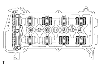
Check the valves indicated in the illustration.
Using a feeler gauge, measure the clearance between the valve lifter and camshaft.
Valve clearance (cold):
for intake:
0.15 to 0.25 mm (0.006 to 0.010 in.)
for exhaust:
0.25 to 0.35 mm (0.010 to 0.014 in.)
Record any out-of-specification valve clearance measurements. They will be used later to determine the required replacement adjusting shim.
Turn the crankshaft 1 complete revolution (360°) and align its timing notch with the timing mark "0" of the oil pump.
Check the valves indicated in the illustration.
Using a feeler gauge, measure the clearance between the valve lifter and camshaft.
Valve clearance (cold):
for intake:
0.15 to 0.25 mm (0.006 to 0.010 in.)
for exhaust:
0.25 to0.35 mm (0.010 to 0.014 in.)
Record any out-of-specification valve clearance measurements. They will be used later to determine the required replacement adjusting shim.
3.
ADJUST VALVE CLEARANCE
Remove the 2 bolts and remove the No. 2 timing chain or belt cover.
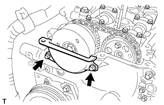
Turn the crankshaft pulley clockwise and remove the 2 bolts.
Turn the crankshaft pulley clockwise and align the timing mark (cutout) with the 0 degree position on the timing chain cover.
Make sure that the timing marks of the camshaft timing sprocket and the camshaft timing gear are in the positions shown in the illustration.
HINT:
If the timing marks are not aligned, turn the crankshaft 1 complete revolution and align the marks as above.
Place paint marks on the chain plate corresponding to the timing marks of the camshaft timing gear and the camshaft timing sprocket.
Using the hexagonal portion of the camshaft, loosen the camshaft timing sprocket fixing bolt.
Using a socket hexagonal wrench 10, remove the chain cover service hole screw plug.
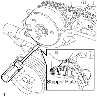
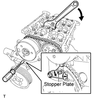
Using a screwdriver, pull down the stopper plate of the tensioner from the chain tensioner service hole and hold it.
HINT:
If the lock of the stopper plate is hard to release, using the hexagonal portion of the camshaft, turn the camshaft slightly both ways.
Using the hexagonal portion of the camshaft, turn the camshaft slightly clockwise and hold it.
HINT:
The plunger of the tensioner is pushed by turning the camshaft clockwise.
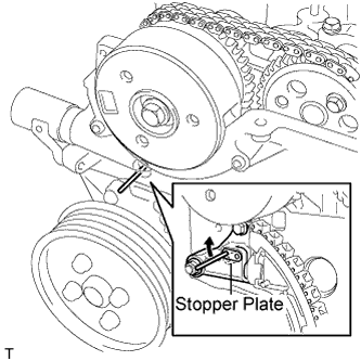
Remove the screwdriver from the chain tensioner service hole, then align the holes in the stopper plate and the tensioner and insert a 3 mm diameter bar into the holes to hold the stopper plate.
NOTICE:
If the 3 mm diameter bar is hard to insert into the holes, turn the camshaft slightly counterclockwise and clockwise.
Using the hexagonal portion of the camshaft, hold the camshaft.
Securely hold the bar with tape so that the bar does not come off.
Remove the installation bolt from the camshaft timing gear or sprocket and remove the sprocket from the exhaust camshaft.
Remove the bolt and remove the camshaft timing sprocket assembly.
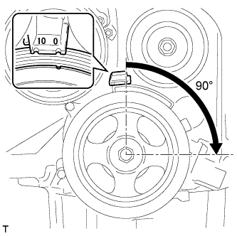
Turn the crankshaft pulley 90 degrees as shown in the illustration
NOTICE:
When turning the camshaft with the chain removed, turn the crankshaft 90 degrees clockwise to avoid it interfering with the piston when the valve is fully open. Make sure that the cutout of the crankshaft pulley is in the position shown in the illustration.
Remove the 4 bolts and camshaft bearing cap.
Using the hexagonal head portion of the camshaft, revolve the camshaft so that the cam noses of cylinders No. 2 and No. 4 face as shown in the illustration.
Remove the camshaft bearing caps and bolts shown in the sequence in the illustration.
Remove the exhaust camshaft assembly and camshaft timing gear.
Using the hexagonal head portion of the camshaft, revolve the camshaft so that the cam noses of cylinders No. 3 and No. 4 face as shown in the illustration.
Remove the camshaft bearing caps and bolts in the sequence shown in the illustration.
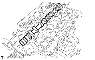
Remove the camshaft.
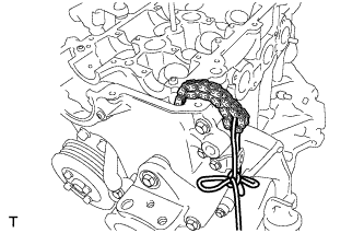
Fix the chain with a piece of rope or wire.
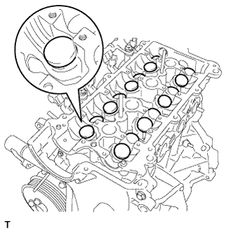
Remove the valve lifters.
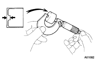
Using a micrometer, measure the thickness of the removed lifter.
Calculate the thickness of a new lifter so that the valve clearance comes to within the specified values.
A
Thickness of new lifter
B
Thickness of used lifter
C
Measured valve clearance
Valve clearance:
Intake A = B + (C - 0.18 mm (0.007in.))
Exhaust A = B + (C - 0.25 mm (0.010in.))
Select a new lifter with a thickness as close to the calculated values as possible.
HINT:
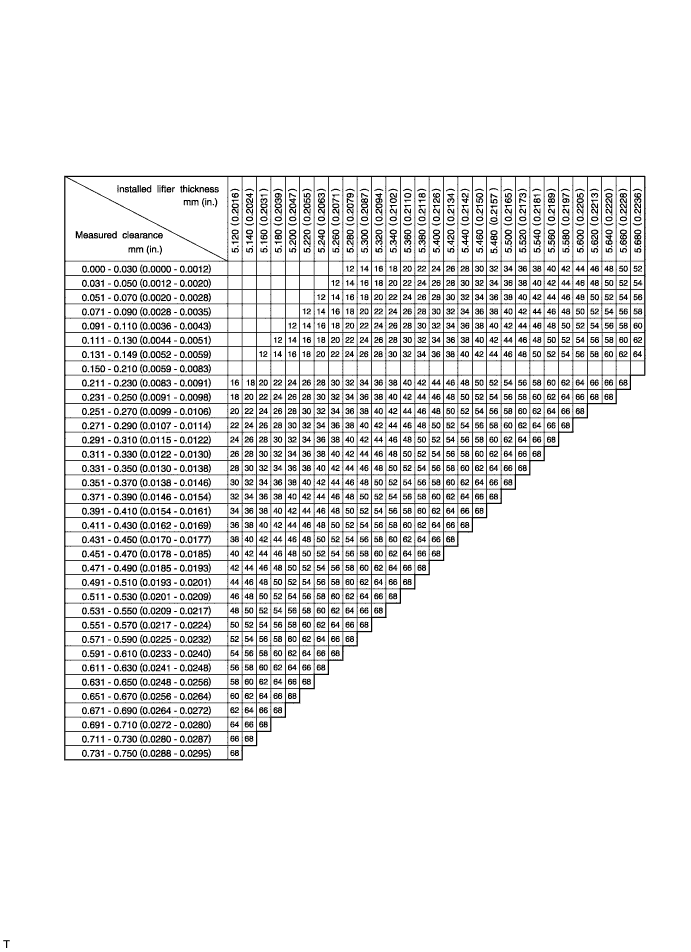
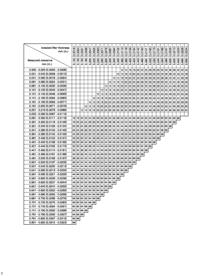
Lifters are available in 29 sizes in increments of 0.020 mm (0.0008 in.), from 5.120 mm (0.2016 in.) to 5.680 mm (0.2228 in.).
Intake valve clearance (Cold):
0.145 to 0.235 mm (0.00571 to 0.00925 in.)
EXAMPLE:
The 5.260 mm (0.2071 in.) lifter is installed, and the measured clearance is 0.400 mm (0.0157 in.).
Replace the 5.260 mm (0.2071 in.) lifter with a new No. 48 lifter.
New lifter thickness
Lifter No.
Thickness
Lifter No.
Thickness
Lifter No.
Thickness
12
5.120 (0.2016)
32
5.320 (0.2094)
52
5.520 (0.2173)
14
5.140 (0.2024)
34
5.340 (0.2102)
54
5.540 (0.2181)
16
5.160 (0.2031)
36
5.360 (0.2110)
56
5.560 (0.2189)
18
5.180 (0.2039)
38
5.380 (0.2118)
58
5.580 (0.2197)
20
5.200 (0.2047)
40
5.400 (0.2126)
60
5.600 (0.2205)
22
5.220 (0.2055)
42
5.420 (0.2134)
62
5.620 (0.2213)
24
5.240 (0.2063)
44
5.440 (0.2142)
64
5.640 (0.2220)
26
5.260 (0.2071)
46
5.460 (0.2150)
66
5.660 (0.2228)
28
5.280 (0.2079)
48
5.480 (0.2157)
68
5.680 (0.2236)
30
5.300 (0.2087)
50
5.500 (0.2165)
Exhaust valve clearance (Cold):
0.215 to 0.305 mm (0.00492 to 0.01201 in.)
EXAMPLE:
The 5.340 mm (0.2102 in.) lifter is installed, and the measured clearance is 0.440 mm (0.0173 in.).
Replace the 5.340 mm (0.2102 in.) lifter with a new No. 52 lifter.
New lifter thickness
Lifter No.
Thickness
Lifter No.
Thickness
Lifter No.
Thickness
12
5.120 (0.2016)
32
5.320 (0.2094)
52
5.520 (0.2173)
14
5.140 (0.2024)
34
5.340 (0.2102)
54
5.540 (0.2181)
16
5.160 (0.2031)
36
5.360 (0.2110)
56
5.560 (0.2189)
18
5.180 (0.2039)
38
5.380 (0.2118)
58
5.580 (0.2197)
20
5.200 (0.2047)
40
5.400 (0.2126)
60
5.600 (0.2205)
22
5.220 (0.2055)
42
5.420 (0.2134)
62
5.620 (0.2213)
24
5.240 (0.2063)
44
5.440 (0.2142)
64
5.640 (0.2220)
26
5.260 (0.2071)
46
5.460 (0.2150)
66
5.660 (0.2228)
28
5.280 (0.2079)
48
5.480 (0.2157)
68
5.680 (0.2236)
30
5.300 (0.2087)
50
5.500 (0.2165)
Install the selected valve lifter.
Apply new engine oil to the valve lifter and journal of the cylinder head.
Place the intake camshaft on the cylinder head so that the cam nose of cylinders No. 3 and No. 4 face as shown in the illustration.
Apply new engine oil to the lifter and journal of the cylinder head.
Place the exhaust camshaft on the cylinder head so that the cam noses of cylinders No. 2 and No. 4 face as shown in the illustration.
Install the intake camshaft bearing caps with 8 bolts.
Install the exhaust camshaft bearing caps with 8 bolts.
Provisionally install the camshaft bearing cap and the bolt as shown in the illustration.
Uniformly tighten the 20 bolts in the sequence shown in the illustration.
Torque:
13 N*m{
130 kgf*cm
, 10 ft.*lbf
}
Make sure that the timing marks of the camshaft timing sprocket and the camshaft timing gear are in the positions shown in the illustration.
Make sure that the timing mark (cutout) of the crankshaft pulley is in the position shown in the illustration.
Align the marks of the camshaft timing sprocket and the chain and install the camshaft timing gear or sprocket.
Align the knock pin of the camshaft with the pin hole in the camshaft timing sprocket and install the camshaft timing sprocket onto the camshaft.
NOTICE:
If the knock pin and the pin hole are not aligned, using the hexagonal portion of the camshaft, slightly turn the camshaft both ways and align them. Do not apply excessive force to the camshaft timing sprocket during the alignment, otherwise, the tip of the knock pin could damage the seal surface.
Apply a small amount of engine oil to the screw and seat surface of the camshaft timing sprocket installation bolt.
Using the hexagonal portion of the camshaft, install the camshaft timing sprocket.
Torque:
47 N*m{
480 kgf*cm
, 35 ft.*lbf
}
Align the marks of the camshaft timing gear or sprocket and the chain and install the chain onto the camshaft timing gear or sprocket.
Align the knock pin of camshaft No. 2 with the pin hole in the camshaft timing gear or sprocket and install the camshaft timing gear or sprocket onto camshaft No. 2.
HINT:
If the pin and pin hole are not aligned, using the hexagonal portion of the camshaft, slightly turn the camshaft both ways and align them.
Provisionally tighten the bolt of camshaft No. 2 indicated by the arrow in the illustration.
Remove the 3mm diameter bar from the chain tensioner.
NOTICE:
Using the hexagonal portion of the camshaft, slightly turn the camshaft counterclockwise and remove the 3mm diameter bar with the chain on the tensioner loose.
Make sure that the timing mark (cutout) of the crankshaft pulley is in the position shown in the illustration.
Make sure that the timing marks of the camshaft timing sprocket and the camshaft timing gear or sprocket are in the positions shown in the illustration.
Apply adhesive 1234 to the 2 or 3 threads at the tip of the bolt of the chain cover service hole screw plug.
NOTICE:
Keep the bolt and bolt hole free of foreign matter and oil.
Using a socket hexagon wrench 10, install the chain cover service hole screw plug.
Torque:
17 N*m{
173 kgf*cm
, 13 ft.*lbf
}
Turn the crankshaft pulley clockwise and provisionally install the camshaft timing gear or sprocket with the 2 camshaft timing gear fixing bolts indicated by the arrow in the illustration. Then tighten it to the specified torque with the 3 bolts.
Torque:
8.0 N*m{
82 kgf*cm
, 71 in.*lbf
}
4.
INSTALL NO. 2 TIMING CHAIN OR BELT COVER
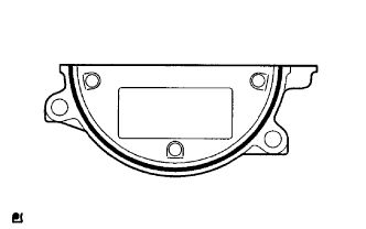
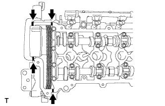
Apply seal packing black to the area shown in the illustration.
Seal Packing:
Toyota genuine seal packing black, Three bond 12078B or Equivalent.
NOTICE:
Keep the installation surface free of foreign matter and oil.
Install the No. 2 timing chain or belt cover within 3 minutes of applying the seal packing.
Do not start the engine for at least 2 hours after the installation.
Install timing chain cover No. 2 with the 2 bolts.
Torque:
8.5 N*m{
87 kgf*cm
, 75 in.*lbf
}
5.
INSTALL CYLINDER HEAD COVER SUB-ASSEMBLY
Apply seal packing black to the area shown in the illustration.
Seal Packing:
Toyota genuine seal packing black, Three bond 12078B or Equivalent.
NOTICE:
Keep the installation surface free of foreign matter and oil.
Install the No. 2 timing chain or belt cover within 3 minutes of applying the seal packing.
Do not start the engine for at least 2 hours after the installation.
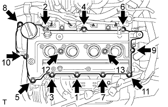
Using the several steps, install the cylinder head cover with the 11 bolts and the nut.
Torque:
11 N*m{
112 kgf*cm
, 8 ft.*lbf
}
6.
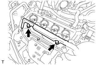
CONNECT ENGINE WIRE (for RHD)
Connect the engine wire harness with the 2 bolts..
Torque:
8.0 N*m{
82 kgf*cm
, 71 in.*lbf
}
Connect the engine wire harness clamp.
7.
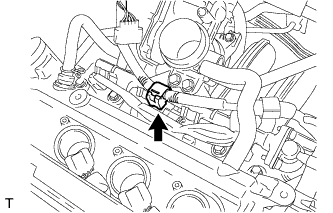
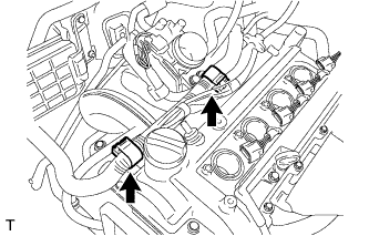
CONNECT ENGINE WIRE (for LHD)
Install the engine wire harness with the 2 bolts.
Torque:
8.0 N*m{
82 kgf*cm
, 71 in.*lbf
}
Connect the 2 engine wire harness clamps.
8.
INSTALL OIL LEVEL GAGE SUB-ASSEMBLY
9.
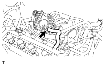
INSTALL NO. 2 VENTILATION HOSE
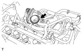
Connect the No. 2 ventilation hose to the throttle body assembly.
10.
INSTALL VENTILATION HOSE
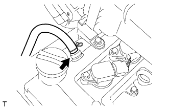
Connect the ventilation hose to the positive crankcase ventilation valve.
11.
INSTALL IGNITION COIL ASSEMBLY
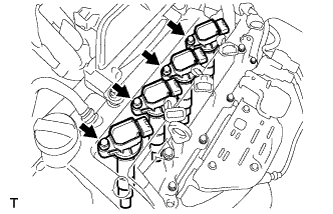
Install the 4 ignition coil assembly with the 4 bolts.
Torque:
7.5 N*m{
77 kgf*cm
, 66 in.*lbf
}
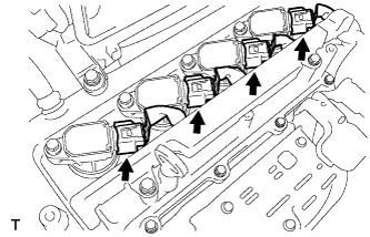
Connect the 4 ignition coil assembly connectors.
12.
INSTALL AIR CLEANER ASSEMBLY
Install a new O-ring.
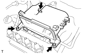
Install the air cleaner case sub-assembly with the 3 bolts.
Torque:
7.5 N*m{
76 kgf*cm
, 66 in.*lbf
}
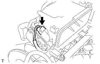
Connect the connector to the mass air flow meter.
13.
INSTALL PURGE VSV ASSEMBLY
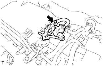
Install the bolt and install the purge VSV assembly.
Torque:
8.0 N*m{
82 kgf*cm
, 71 in.*lbf
}
14.
CHECK FOR ENGINE OIL LEAKAGE
15.
CONNECT CABLE TO NEGATIVE BATTERY TERMINAL
Torque:
5.4 N*m{
55 kgf*cm
, 48 in.*lbf
}
16.
INSTALL AIR CLEANER FILTER ELEMENT SUB-ASSEMBLY
17.
INSTALL AIR CLEANER CAP SUB-ASSEMBLY
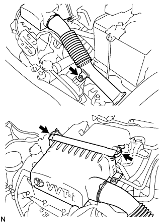
Install the air cleaner cap with the grommet and 2 clamps.