Removal / installation · Vehicles built from Nov 2005
1.
DISCONNECT CABLE FROM NEGATIVE BATTERY TERMINAL
2.
REMOVE ENGINE UNDER COVER RH
3.
REMOVE AIR CLEANER CAP SUB-ASSEMBLY
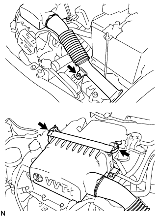
Remove the grommet and 2 clamps and remove the air cleaner cap sub-assembly.
4.
REMOVE AIR CLEANER FILTER ELEMENT SUB-ASSEMBLY
5.
REMOVE PURGE VSV ASSEMBLY
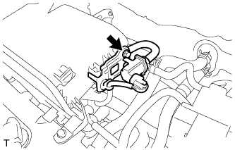
Remove the bolt and remove the purge VSV assembly.
6.
REMOVE AIR CLEANER ASSEMBLY
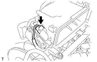
Disconnect the mass air flow meter connector.
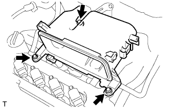
Remove the 3 bolts and remove the air cleaner case sub-assembly.
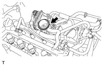
Remove the O-ring from the throttle body assembly.
7.
REMOVE IGNITION COIL ASSEMBLY
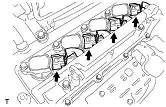
Disconnect the 4 ignition coil assembly connectors.
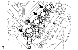
Remove the 4 bolts and 4 ignition coils.
8.
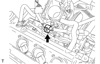
REMOVE VENTILATION HOSE
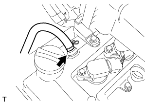
Disconnect the ventilation hose from the positive crankcase ventilation valve.
9.
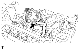
REMOVE NO. 2 VENTILATION HOSE
Disconnect the No. 2 ventilation hose from the throttle body assembly.
10.
REMOVE OIL LEVEL GAGE SUB-ASSEMBLY
11.
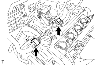
DISCONNECT ENGINE WIRE (for LHD)
Disengage the 2 engine wire harness clamps.
Remove the 2 bolts and disconnect the engine wire harness.
12.
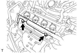
DISCONNECT ENGINE WIRE (for RHD)
Disengage the engine wire harness clamp.
Remove the 2 bolts and disconnect the engine wire harness.
13.
REMOVE CYLINDER HEAD COVER SUB-ASSEMBLY
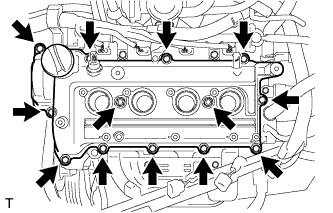
Remove the 11 bolts, 2 nuts and 2 seal washers and remove the cylinder head cover.
14.
REMOVE NO. 2 TIMING CHAIN OR BELT COVER
Remove the 2 bolts and remove the No. 2 timing chain or belt cover.
15.
REMOVE NO. 2 CAMSHAFT
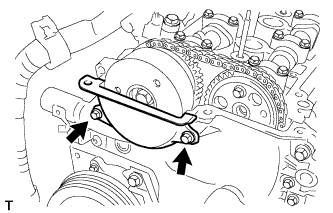
Turn the crankshaft pulley clockwise and remove the 2 bolts.
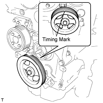
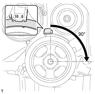
Turn the crankshaft pulley clockwise and align the timing mark (cutout) in the position shown in the illustration.
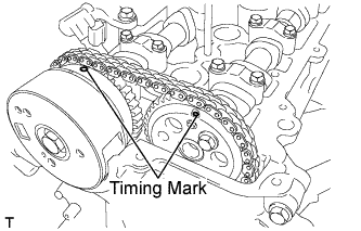
Make sure that the timing marks of the camshaft timing sprocket and the camshaft timing gear are in the positions shown in the illustration.
HINT:
If the timing marks are not aligned, turn the crankshaft 1 complete revolution and align the marks as above.
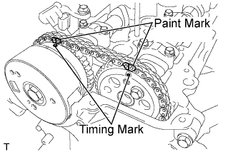
Place paint marks on the chain plate corresponding to the timing marks of the camshaft timing gear and the camshaft timing sprocket.
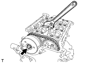
Using the hexagonal portion of the camshaft, loosen the camshaft timing sprocket fixing bolt.
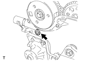
Using a socket hexagonal wrench 10, remove the chain cover service hole screw plug.
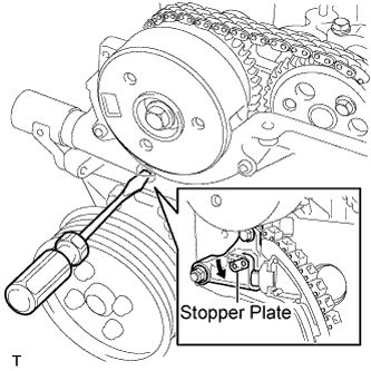
Using a screwdriver, pull down the stopper plate of the tensioner from the chain tensioner service hole and hold it.
HINT:
If the lock of the stopper plate is hard to release, using the hexagonal portion of the camshaft, turn the camshaft slightly both ways.
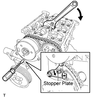
Using the hexagonal portion of the camshaft, turn the camshaft slightly clockwise and hold it.
HINT:
The plunger of the tensioner is pushed by turning the camshaft clockwise.
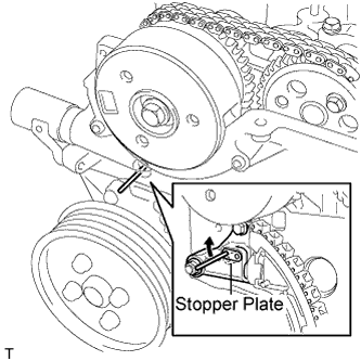
Remove the screwdriver from the chain tensioner service hole, then align the holes in the stopper plate and the tensioner and insert a 3mm (0.118 in.) diameter bar into the holes to hold the stopper plate.
NOTICE:
If the 3mm (0.118 in.) diameter bar is hard to insert into the holes, turn the camshaft slightly counterclockwise and clockwise.
Using the hexagonal portion of the camshaft, hold the camshaft.
Securely hold the bar with tape so that the bar does not come off.
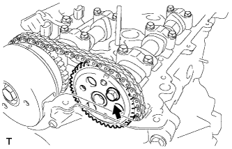
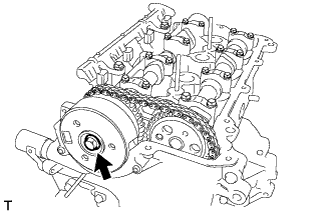
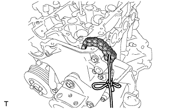
Remove the fixing bolt of the camshaft timing gear or sprocket and remove the sprocket from the exhaust camshaft.
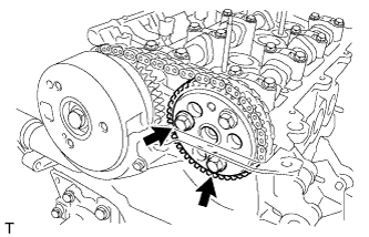
Remove the bolt and remove the camshaft timing sprocket assembly.
Turn the crankshaft pulley 90°clockwise as shown.
NOTICE:
When turning the camshaft with the chain removed, turn the crankshaft 90 degrees clockwise to avoid it interfering with the piston when the valve is fully open. Make sure that the cutout of the crankshaft pulley is in the position shown in the illustration.
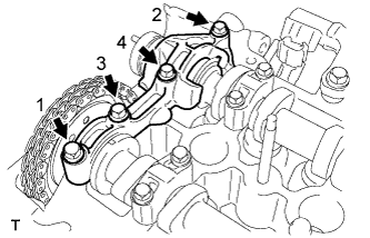
Remove the 4 bolts and camshaft bearing cap.
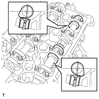
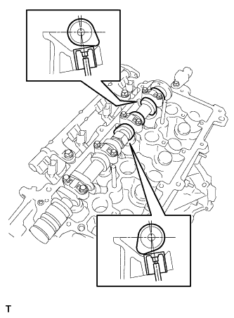
Using the hexagonal head portion of the camshaft, revolve the camshaft so that the cam noses of cylinders No. 2 and No. 4 face as shown in the illustration.
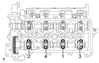
Remove the camshaft bearing caps and bolts in the sequence shown in the illustration.
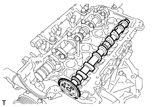
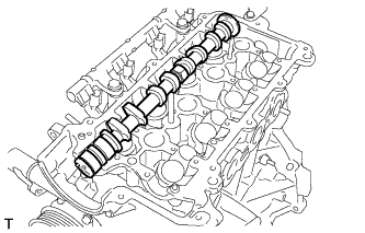
Remove the exhaust camshaft.
16.
REMOVE CAMSHAFT
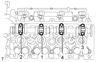
Using the hexagonal head portion of the camshaft, revolve the camshaft so that the cam noses of cylinders No. 3 and No. 4 face as shown in the illustration.
Remove the camshaft bearing caps and bolts in the sequence shown in the illustration.