INSTALLATION
Removal / installation · Vehicles built from Nov 2005
| 1. INSTALL CHAIN SUB-ASSEMBLY |

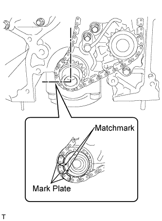  |
Align the matchmarks of the crankshaft sprocket and the timing chain and install the timing chain.
Align the matchmarks of the camshaft timing sprocket and the camshaft timing gear or sprocket with the timing marks of the timing chain and install the timing chain.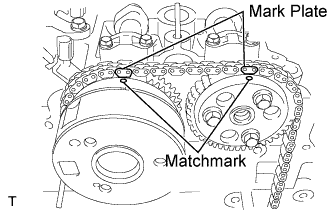
| 2. INSTALL NO. 2 TIMING CHAIN GUIDE |
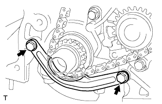 |
Install the No. 2 timing chain guide with the 2 bolts.
- Torque:
- 12 N*m{ 122 kgf*cm , 9 ft.*lbf }
| 3. INSTALL TIMING CHAIN GUIDE |
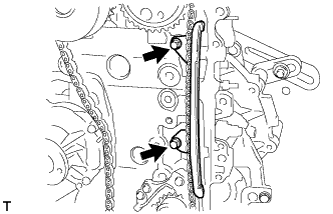 |
Install the timing chain guide with the 2 bolts.
- Torque:
- 7.5 N*m{ 76 kgf*cm , 66 in.*lbf }
| 4. INSTALL TIMING CHAIN TENSION ARM |
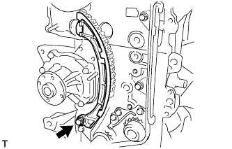 |
Install the timing chain tension arm with the bolt.
- Torque:
- 19 N*m{ 194 kgf*cm , 14 ft.*lbf }
| 5. INSTALL CHAIN TENSIONER PLUNGER |
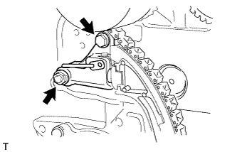 |
Install the chain tensioner plunger with the bolt and the nut.
- Torque:
- 9.0 N*m{ 92 kgf*cm , 80 in.*lbf }
- NOTICE:
- Using the hexagonal portion of the camshaft, slightly turn the camshaft counterclockwise and install the tensioner plunger with the chain on the tensioner loose.
Remove the 3mm diameter bar from the chain tensioner plunger.
| 6. INSTALL NO. 1 CRANKSHAFT POSITION SENSOR PLATE |
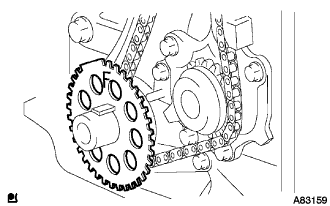 |
Install the No. 1 crankshaft position sensor plate so that mark F can be seen.
| 7. INSTALL TIMING CHAIN OR BELT COVER OIL SEAL |
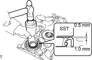 |
Using SST, tap in a new oil seal to the specified depth.
- SST
- 09636-20010
- NOTICE:
- Do not tap in the oil seal at an angle.
Apply a small amount of MP grease to the lip of the new oil seal.
- NOTICE:
- Keep the lip free of foreign matter.
| 8. INSTALL TIMING CHAIN OR BELT COVER SUB-ASSEMBLY |
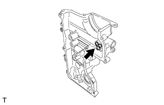 |
Install a new gasket onto the timing chain cover.
Apply seal packing black as shown in the illustration.
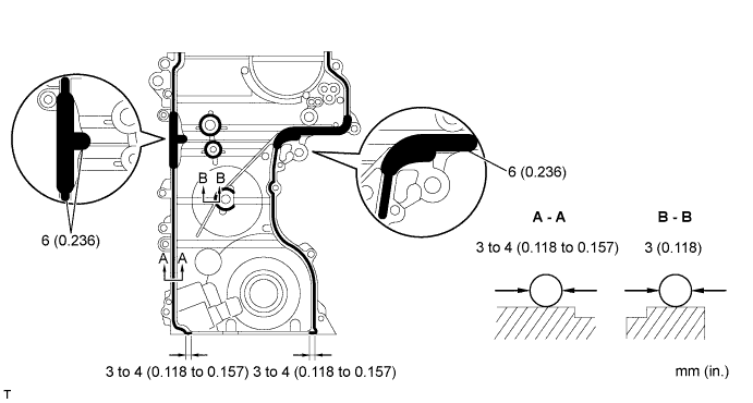
- Seal packing:
- Toyota genuine seal packing black, Three bond 12078B or Equivalent.
- NOTICE:
- Remove any oil from the contact surfaces.
- Install the oil pump assembly within 3 minutes and tighten the bolts and nut within 15 minutes of applying the seal packing.
- Do not expose the seal to engine oil for at least 2 hours after the installation.
- Remove any oil from the contact surfaces.
Install the 10 bolts, nut and 2 bolts.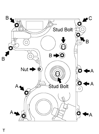
- Torque:
- 12 N*m{ 122 kgf*cm , 9 ft.*lbf } bolt A or B
- 23 N*m{ 238 kgf*cm , 17 ft.*lbf } bolt C
- 12 N*m{ 122 kgf*cm , 9 ft.*lbf } nut
- 4.0 N*m{ 41 kgf*cm , 35 in.*lbf } stud bolt
- HINT:
- Each bolt length is as follows.
- A: 10 mm (0.394 in.)
- B: 30 mm (1.181 in.)
- C: 35 mm (1.378 in.)
- A: 10 mm (0.394 in.)
| 9. INSTALL TRANSVERSE ENGINE ENGINE MOUNTING BRACKET |
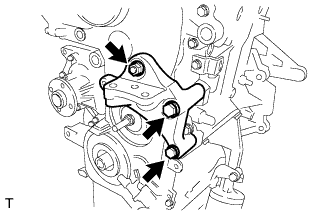 |
Install the engine mounting bracket with the 2 bolts and nut.
- Torque:
- 42 N*m{ 428 kgf*cm , 31 ft.*lbf }
| 10. INSTALL ENGINE MOUNTING STAY RH |
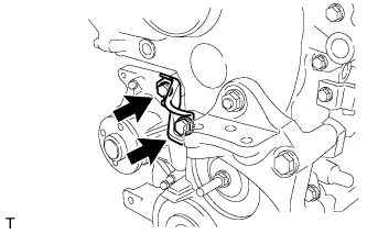 |
Install the engine mounting stay with the 2 bolts.
- Torque:
- 18 N*m{ 184 kgf*cm , 13 ft.*lbf }
| 11. INSTALL FAN AND GENERATOR V BELT |
Provisionally install the V belt onto the pulleys.
| 12. INSTALL TRANSVERSE ENGINE ENGINE MOUNTING INSULATOR |
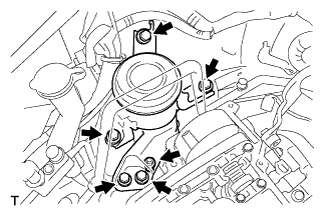 |
Install the engine mounting insulator with the 5 bolts and nut.
- Torque:
- 52 N*m{ 530 kgf*cm , 38 ft.*lbf }
Install the low pressure pipe bracket of the air conditioner with the bolt.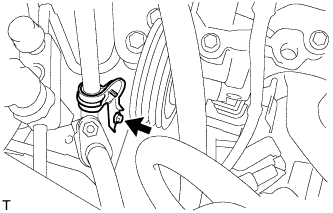
Install the engine mounting insulator.
- Torque:
- 10 N*m{ 100 kgf*cm , 7 ft.*lbf }
Remove the engine hanger with the bolt.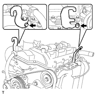
| 13. INSTALL OIL PAN SUB-ASSEMBLY |
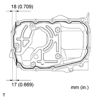 |
Apply seal packing black (Diameter 4.0 mm 0.157 in.) to the area shown in the illustration.
- Seal Packing:
- Toyota genuine seal packing black, Three bond 12078B or Equivalent.
- NOTICE:
- Keep the installation surfaces free of oil.
- Install the oil pan within 3 minutes of applying the seal packing black.
- Install the oil pan to the specified torque within 15 minutes of applying the seal packing black.
- Do not start the engine for at least 2 hours after the installation.
- Keep the installation surfaces free of oil.
Install the oil pan with the 2 nuts and 16 bolts.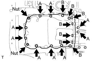
- Torque:
- 9.0 N*m{ 92 kgf*cm , 80 in.*lbf } bolt A
- 41 N*m{ 413 kgf*cm , 30 ft.*lbf } bolt B
- 13 N*m{ 133 kgf*cm , 10 ft.*lbf } nut
Install the service hole cover.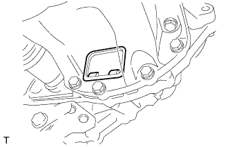
| 14. INSTALL CAM TIMING OIL CONTROL VALVE ASSEMBLY |
Install the cam timing oil control valve assembly with the bolt.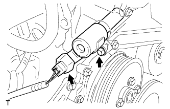
- Torque:
- 7.5 N*m{ 76 kgf*cm , 66 in.*lbf }
Connect the connector.
| 15. INSTALL NO. 2 IDLER PULLEY SUB-ASSEMBLY (w/ Air Conditioning System) |
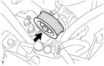 |
Install the washer and pulley with the bolt and nut.
- Torque:
- 44 N*m{ 449 kgf*cm , 33 ft.*lbf }
| 16. INSTALL CRANK SHAFT POSITION SENSOR |
Install the crankshaft position sensor with the bolt.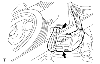
- Torque:
- 7.5 N*m{ 76 kgf*cm , 66 in.*lbf }
Connect the crankshaft position sensor connector.
| 17. INSTALL IDLER PULLEY SUB-ASSEMBLY (w/ Air Conditioning System) |
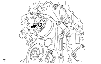 |
Install the washer and pulley with the nut.
- Torque:
- 44 N*m{ 449 kgf*cm , 33 ft.*lbf }
| 18. INSTALL WATER PUMP PULLEY |
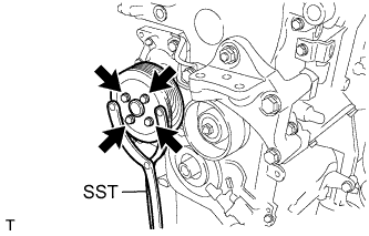 |
Using SST, hold the water pump pulley and install the water it pump pulley with the 4 bolts.
- Torque:
- 12 N*m{ 117 kgf*cm , 9 ft.*lbf }
- SST
- 09960-10010
(09963-00500)
| 19. INSTALL CRANKSHAFT PULLEY |
w/o service hole: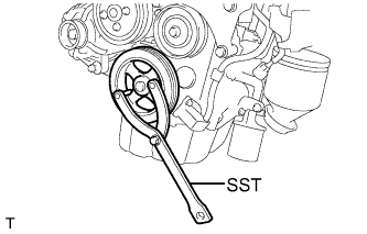
Hold the crankshaft pulley with SST and tighten the bolt.
- SST
- 09960-10010
(09963-00500)
- Torque:
- 150 N*m{ 1530 kgf*cm , 111 ft.*lbf }
w/ service hole: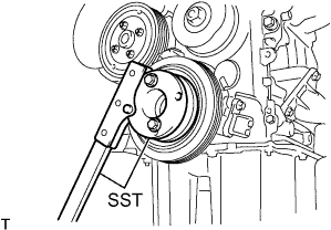
Hold the crankshaft pulley with SST and tighten the bolt.
- SST
- 09330-00021
09213-54015 (91651-60855)
- Torque:
- 150 N*m{ 1530 kgf*cm , 111 ft.*lbf }
| 20. INSTALL CYLINDER HEAD COVER SUB-ASSEMBLY |
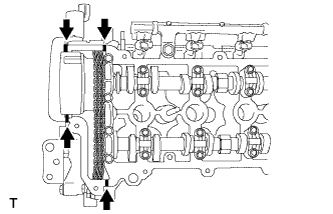 |
Apply seal packing black to the area shown in the illustration.
- Seal Packing:
- Toyota genuine seal packing black, Three bond 12078B or Equivalent.
- NOTICE:
- Keep the installation surface free of foreign matter and oil.
- Install the No. 2 timing chain or belt cover within 3 minutes of applying the seal packing.
- Do not start the engine for at least 2 hours after the installation.
- Keep the installation surface free of foreign matter and oil.
Using the several steps, install the cylinder head cover with the 11 bolts and the nut.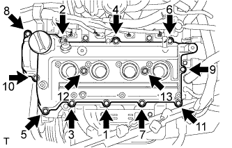
- Torque:
- 11 N*m{ 112 kgf*cm , 8 ft.*lbf }
| 21. CONNECT ENGINE WIRE (for RHD) |
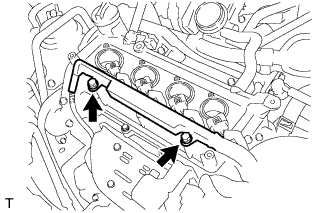 |
Connect the engine wire harness with the 2 bolts..
- Torque:
- 8.0 N*m{ 82 kgf*cm , 71 in.*lbf }
Connect the engine wire harness clamp.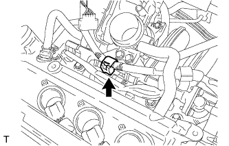
| 22. CONNECT ENGINE WIRE (for LHD) |
|
|
Install the engine wire harness with the 2 bolts.
- Torque:
- 8.0 N*m{ 82 kgf*cm , 71 in.*lbf }
Connect the 2 engine wire harness clamps.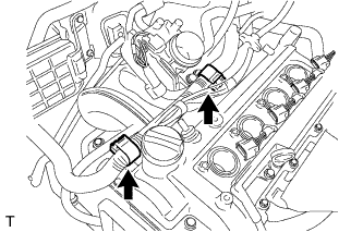
| 23. INSTALL OIL LEVEL GAGE SUB-ASSEMBLY |
| 24. CONNECT NO. 2 VENTILATION HOSE |
Connect the No. 2 ventilation hose to the cylinder head.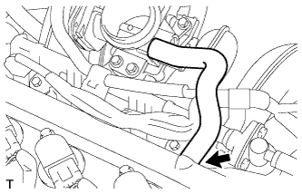
| 25. CONNECT VENTILATION HOSE |
Connect the ventilation hose to the cylinder head.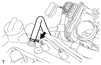
| 26. INSTALL IGNITION COIL ASSEMBLY |
Install the 4 ignition coil assembly with the 4 bolts.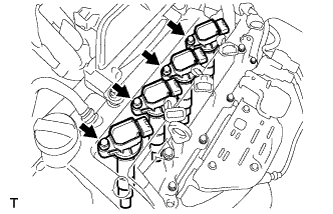
- Torque:
- 7.5 N*m{ 77 kgf*cm , 66 in.*lbf }
Connect the 4 ignition coil assembly connectors.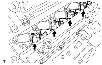
| 27. CONNECT CABLE TO NEGATIVE BATTERY TERMINAL |
- Torque:
- 5.4 N*m{ 55 kgf*cm , 48 in.*lbf }
| 28. ADD ENGINE COOLANT |
Tighten all the plugs.
Disconnect the vinyl hose.
Pour engine coolant into the radiator assembly until it overflows.
- Capacity:
- 5.1 liters (5.4 USqts, 4.5 lmp. qts)
- NOTICE:
- Do not substitute plain water for engine coolant.
- HINT:
- Use of improper engine coolant may damage the engine coolant system.
- Use only Toyota Super Long Life Coolant or similar high quality ethylene glycol based non-silicate, non-amine, non-nitrite, and non-borate engine coolant with long-life hybrid organic acid technology (coolant with long-life hybrid organic acid technology consists of a combination of low phosphates and organic acids).
- Use of improper engine coolant may damage the engine coolant system.
Check the engine coolant level inside the radiator assembly by squeezing the inlet and outlet radiator hoses several times by hand. If the engine coolant level goes down, add engine coolant.
Install the radiator cap sub-assembly securely.
Slowly pour engine coolant into the radiator reservoir until it reaches the FULL line.
Warm up the engine until the cooling fan operates.
Set the air conditioning as follows while warming up the engine.
Item
Manual air conditioning system
Automatic air conditioning system
Set control as follows
Fan speed - Any setting except "OFF"
Temperature - Toward WARM
Air conditioning switch "OFF"
Fan speed - Any setting except "OFF"
Temperature - To the highest temperature
Air conditioning switch "OFF"
"AUTO" switch "OFF"
Maintain the engine speed at 2,000 to 2,500 rpm and warm up the engine until the cooling fan operates.
Stop the engine and wait until the coolant cools down.
If the engine coolant level is below the full level, perform steps (c) through (h) again and repeat the operation until the engine coolant level stays at the full level.
Recheck the engine coolant level inside the radiator reservoir tank assembly. If it is below the full level, add engine coolant.
| 29. CHECK FOR ENGINE COOLANT LEAKAGE |
- CAUTION:
- To avoid the danger of being burned, do not remove the radiator cap sub-assembly while the engine and radiator assembly are still hot. Thermal expansion will cause hot engine coolant and steam to blow out from the radiator assembly.
Fill the radiator assembly with engine coolant, then attach a radiator cap tester.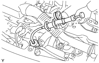
Pump it to 137 kPa (1.4 kgf/cm2, 19.9 psi), then check that the pressure does not drop.
If the pressure drops, check the hoses, radiator assembly and water pump assembly for leakage. If there are no signs or traces of external engine coolant leakage, check the heater core, cylinder block and head.
| 30. CHECK FOR ENGINE OIL LEAKAGE |
| 31. INSTALL AIR CLEANER ASSEMBLY |
Install a new O-ring.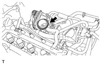
Install the air cleaner case sub-assembly with the 3 bolts.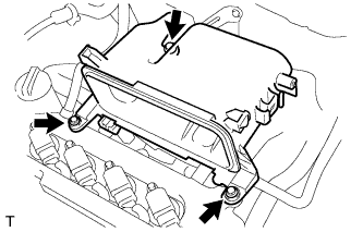
- Torque:
- 7.5 N*m{ 76 kgf*cm , 66 in.*lbf }
Connect the connector to the mass air flow meter.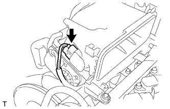
| 32. INSTALL PURGE VSV ASSEMBLY |
Install the bolt and install the purge VSV assembly.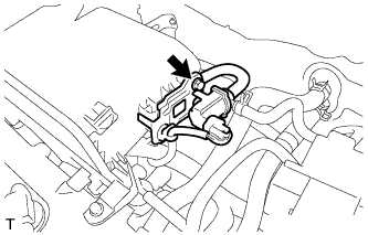
- Torque:
- 8.0 N*m{ 82 kgf*cm , 71 in.*lbf }
| 33. INSTALL AIR CLEANER FILTER ELEMENT SUB-ASSEMBLY |
| 34. INSTALL AIR CLEANER CAP SUB-ASSEMBLY |
Install the air cleaner cap with the grommet and 2 clamps.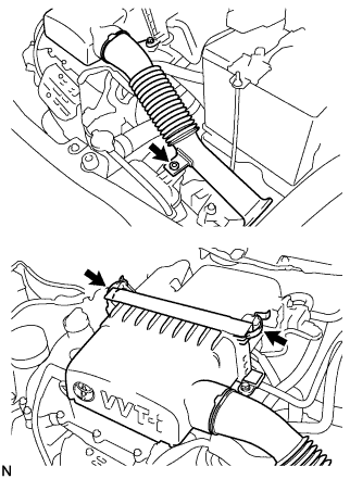
| 35. INSTALL COWL TOP PANEL OUTER |
Install the cowl top panel outer with the 9 bolts.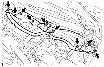
- Torque:
- 6.5 N*m{ 66 kgf*cm , 58 in.*lbf }
Engage the clamp and install the wiper motor connector wire harness.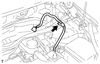
| 36. INSTALL NO. 2 COWL TO REGISTER DUCT SUB-ASSEMBLY |
Engage the 2 claws and install cowl to register duct No. 2.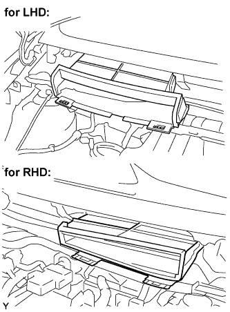
| 37. INSTALL WINDSHIELD WIPER MOTOR ASSY |
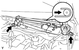 |
Connect the connector.
Slide the wiper link as shown in the illustration and engage the rubber pin with the body.
Install the front wiper motor and link with the 2 bolts.
- Torque:
- 5.5 N*m{ 56 kgf*cm , 49 in.*lbf }
| 38. INSTALL COWL TOP VENTILATOR LOUVER LH (for RHD) |
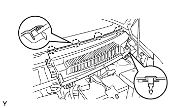 |
Engage the 4 claws and install the cowl top ventilator louver LH.
Install the clip.
| 39. INSTALL COWL TOP VENTILATOR LOUVER SUB-ASSEMBLY (for RHD) |
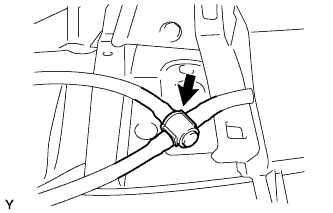 |
Connect the washer hose.
Engage the 11 claws and install the cowl top ventilator louver sub-assembly.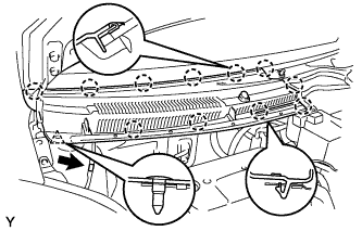
Install the clip.
Connect the washer hose.
Engage the 2 hooks and install cowl top ventilator louver center No. 1.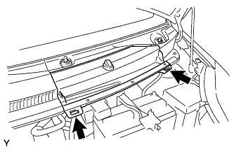
| 40. INSTALL COWL TOP VENTILATOR LOUVER LH (for LHD) |
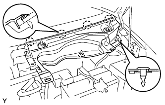 |
Engage the 4 claws and install the cowl top ventilator louver LH.
Install the 2 clips.
| 41. INSTALL COWL TOP VENTILATOR LOUVER SUB-ASSEMBLY (for LHD) |
|
|
Connect the washer hose.
Engage the 11 claws and install the cowl top ventilator louver sub-assembly.
Install the clip.
Connect the washer hose.
Engage the 2 hooks and install cowl top ventilator louver center No. 1.
| 42. INSTALL HOOD TO COWL TOP SEAL |
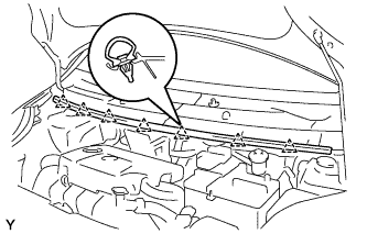 |
Engage the 7 clips and install the hood to cowl top seal.
| 43. INSTALL FRONT WIPER ARM AND BLADE ASSEMBLY RH |
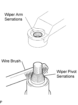 |
Scrape any metal powder off the serrated part of the wiper arm with a round file or the equivalent (when reinstalling).
Clean the wiper pivot serrations with a wire brush.
Operate the wiper, then stop the windshield wiper motor in the automatic stop position.
Align the blade tip with the mark on the windshield glass, as shown in the illustration.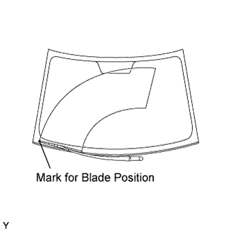
Tighten the nut of the front wiper arm.
- Torque:
- 26 N*m{ 265 kgf*cm , 19 ft.*lbf }
| 44. INSTALL FRONT WIPER ARM AND BLADE ASSEMBLY LH |
|
|
Scrape any metal powder off the serrated part of the wiper arm with a round file or the equivalent (when reinstalling).
Clean the wiper pivot serrations with a wire brush.
Operate the wiper, then stop the windshield wiper motor in the automatic stop position.
Align the blade tip with the mark on the windshield glass, as shown in the illustration.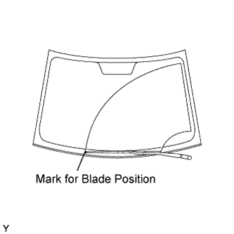
Tighten the nut of the front wiper arm.
- Torque:
- 26 N*m{ 265 kgf*cm , 19 ft.*lbf }
| 45. INSTALL FRONT WIPER ARM HEAD CAP |
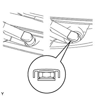 |
Engage the claw and install the 2 front wiper arm head caps.
| 46. INSTALL HOOD SUB-ASSEMBLY |
| 47. INSPECT HOOD SUB-ASSEMBLY |
Check that the clearance measurements are within the standard ranges.
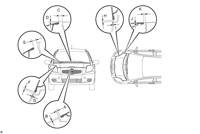
- Standard:
Area
Measurement
Area
Measurement
A
1.7 to 5.7 mm
(0.067 to 0.224 in.)
G
-1.55 to 2.45 mm
(-0.061 to 0.096 in.)
B
-2 to 2 mm
(-0.079 to 0.079 in.)
H
1.75 to 5.75 mm
(0.067 to 0.226 in.)
C
4.45 to 10.45 mm
(0.175 to 0.411 in.)
I
-1.25 to 2.75 mm
(-0.049 to 0.108 in.)
D
-0.95 to 5.05 mm
(-0.037 to 0.199 in.)
J
-1.5 to 1.5 mm
(-0.059 to 0.059 in.)
E
7.55 to 13.55 mm
(0.297 to 0.533 in.)
K
2.0 to 5.0 mm
(0.079 to 0.197 in.)
F
1.65 to 5.65 mm
(0.065 to 0.222 in.)
-
-
| 48. ADJUST HOOD SUB-ASSEMBLY |
Loosen the hood side hinge bolts.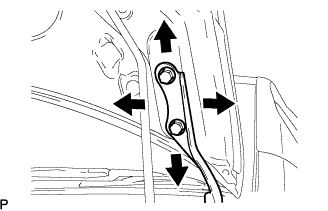
Move the hood to adjust the clearance to within the standard range.
Tighten the hood side hinge bolts after the adjustment.
- Torque:
- 13 N*m{ 133 kgf*cm , 10 ft.*lbf }
Adjust the height of the hood front end by turning the cushion rubber.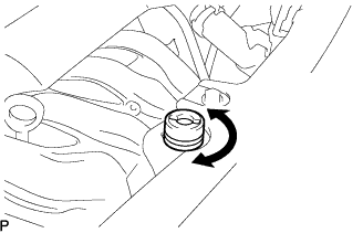
- HINT:
- The cushion rubber can be raised and lowered by turning it.
Adjust the hood lock.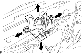
Loosen the 3 bolts.
Adjust the hood lock position so that the striker can enter it smoothly.
Tighten the 3 bolts after the adjustment.
- Torque:
- 7.5 N*m{ 76 kgf*cm , 66 in.*lbf }
| 49. INSTALL FRONT WHEEL |
- Torque:
- 103 N*m{ 1050 kgf*cm , 76 ft.*lbf }
| 50. INSTALL EXHAUST PIPE ASSEMBLY FRONT |
Using vernier calipers, measure the free length of the compression spring.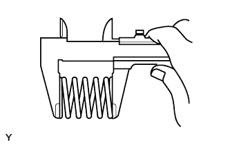
- Minimum length:
- 40.5 mm (1.594 in.)
Using a plastic hammer and a wooden block, tap in a new exhaust pipe gasket until its surface is flush with the exhaust manifold.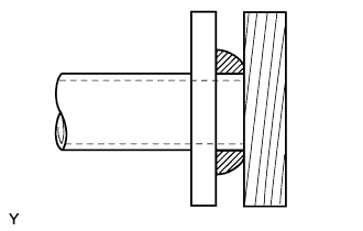
- NOTICE:
- Install the exhaust pipe gasket in the correct direction.
- Do not damage the outer surface of the exhaust pipe gasket.
- Do not reuse the exhaust pipe gasket.
- Do not push in the gasket with the exhaust pipe when connecting it.
- Install the exhaust pipe gasket in the correct direction.
Install the 3 No. 4 exhaust pipe supports.
Install the exhaust pipe assembly front and a new exhaust pipe gasket with the 4 compression springs and 4 bolts.
- Torque:
- 43 N*m{ 439 kgf*cm , 32 ft.*lbf }
| 51. ADJUST FAN AND GENERATOR V BELT |
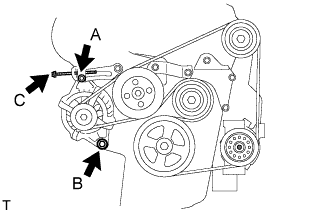 |
Turn adjusting bolt C and adjust the tension of the V-belt.
Tighten fixing bolts A and B.
- Torque:
- 19 N*m{ 194 kgf*cm , 14 ft.*lbf } bolt A
- 44 N*m{ 449 kgf*cm , 33 ft.*lbf } bolt B
| 52. INSPECT FAN AND GENERATOR V BELT |
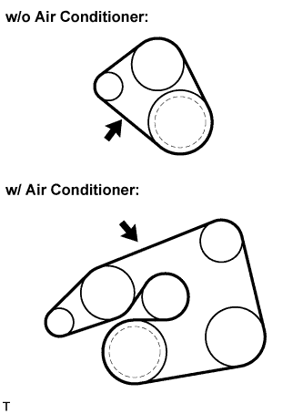 |
Check the V belt deflection and tension.
- Deflection:
Item
Specified Condition
New belt
7.0 to 8.0 mm (0.28 to 0.31 in) w/ air conditioning system
4.0 to 5.0 mm (0.16 to 0.20 in) w/o air conditioning system
Used belt
9.0 to 9.5 mm (0.35 to 0.37 in) w/ air conditioning system
6.0 to 6.5 mm (0.24 to 0.26 in) w/o air conditioning system
- Tension:
Item
Specified Condition
New belt
687 to 883 N (70 to 90 kg, 154 to 199 ld) w/ air conditioning system
785 to 981 N (80 to 100 kg, 176 to 221 ld) w/o air conditioning system
Used belt
539 to 637 N (55 to 65 kg, 121 to 143 ld)
- HINT:
- Check the V belt deflection at the specified point.
- When installing a new belt, set its tension to the specified value.
- When inspecting a belt which has been used for over 5 minutes, apply the Used Belt specifications.
- When reinstalling a belt which has been used for over 5 minutes, adjust its deflection and tension to the intermediate values of each Used Belt specification.
- V-ribbed belt tension and deflection should be checked after 2 revolutions of engine cranking.
- When using a belt tension gauge, confirm its accuracy by using a master gauge first.
- Check the V belt deflection at the specified point.
| 53. CHECK FOR EXHAUST GAS LEAK |
| 54. INSTALL ENGINE UNDER COVER LH |
| 55. INSTALL ENGINE UNDER COVER RH |