REMOVAL
Removal / installation · Vehicles built from Nov 2005
| 1. DISCONNECT CABLE FROM NEGATIVE BATTERY TERMINAL |
| 2. REMOVE ENGINE UNDER COVER RH |
| 3. REMOVE ENGINE UNDER COVER LH |
| 4. DRAIN ENGINE COOLANT |

- CAUTION:
- To avoid the danger of being burned, do not remove the radiator cap sub-assembly while the engine and radiator assembly are still hot. Thermal expansion will cause hot engine coolant and steam to blow out from the radiator assembly.
Install a vinyl hose onto the radiator.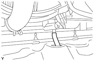

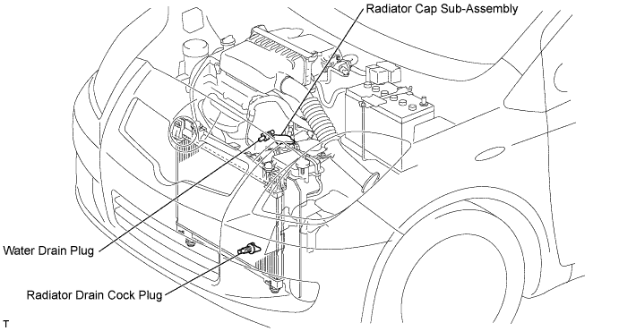
Loosen the radiator drain cock plug.
Remove the radiator cap sub-assembly.
Loosen the water drain plug, then drain the coolant.
| 5. REMOVE FRONT EXHAUST PIPE ASSEMBLY |
Remove the 4 bolts, 4 compression springs.
Remove the 3 exhaust pipe support, No. 4 and the exhaust pipe assembly front.
| 6. REMOVE FRONT WHEEL |
| 7. REMOVE HOOD SUB-ASSEMBLY |
| 8. REMOVE REAR WIPER ARM HEAD CAP |
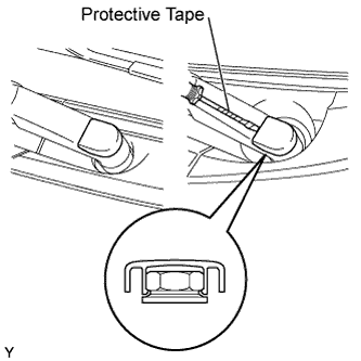 |
Using a screwdriver with its tip wrapped in protective tape, disengage the claw and remove the 2 front wiper arm head caps.
| 9. REMOVE FRONT WIPER ARM AND BLADE ASSEMBLY LH |
Operate the wiper, then stop the windshield wiper motor in the automatic stop position.
Remove the nut and front wiper arm.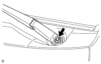
| 10. REMOVE FRONT WIPER ARM AND BLADE ASSEMBLY RH |
- HINT:
- Use the same procedure as for the LH side.
| 11. REMOVE HOOD TO COWL TOP SEAL |
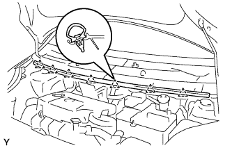 |
Disengage the 7 clips and remove the hood to cowl top seal.
| 12. REMOVE COWL TOP VENTILATOR LOUVER SUB-ASSEMBLY (for LHD) |
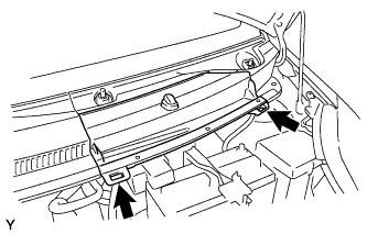 |
Disengage the 2 hooks and remove cowl top ventilator louver center No. 1.
Disconnect the washer hose.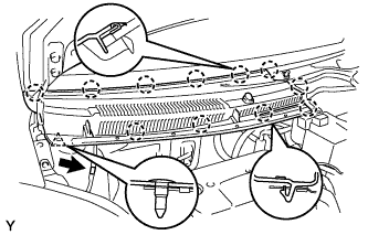
Disengage the 11 claws and clip.
Disconnect the washer hose and remove the cowl top ventilator louver sub-assembly.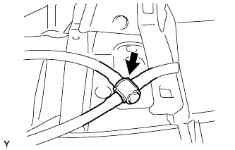
| 13. REMOVE COWL TOP VENTILATOR LOUVER LH (for LHD) |
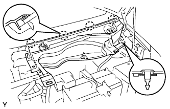 |
Remove the 2 clips.
Disengage the 4 claws and remove the cowl top ventilator louver LH.
| 14. REMOVE COWL TOP VENTILATOR LOUVER SUB-ASSEMBLY (for RHD) |
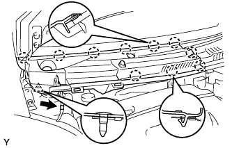 |
Disconnect the washer hose.
Disengage the 10 claws and clip and remove the cowl top ventilator louver sub-assembly.
| 15. REMOVE COWL TOP VENTILATOR LOUVER LH (for RHD) |
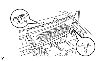 |
Remove the clip.
Disengage the 4 claws and remove the cowl top ventilator louver LH.
| 16. REMOVE WINDSHIELD WIPER MOTOR AND LINK |
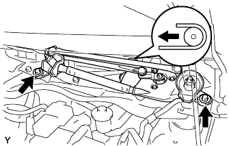 |
Remove the 2 bolts.
Slide the wiper link. Disengage the meshing of the rubber pin, then disconnect the connector and remove the front wiper motor and link.
| 17. REMOVE NO. 2 COWL TO REGISTER DUCT SUB-ASSEMBLY |
Disengage the claws and remove cowl to resister duct No. 2.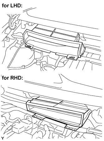
| 18. REMOVE COWL TOP PANEL OUTER |
Disengage the clamp and separate the wiper motor connector.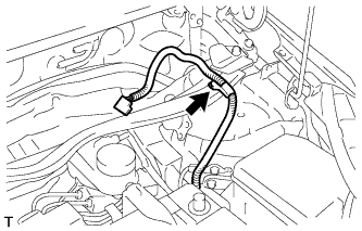
Remove the 9 bolts and the cowl top panel outer.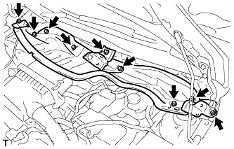
| 19. REMOVE AIR CLEANER CAP SUB-ASSEMBLY |
Remove the grommet and 2 clamps and remove the air cleaner cap sub-assembly.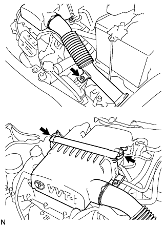
| 20. REMOVE AIR CLEANER FILTER ELEMENT SUB-ASSEMBLY |
| 21. REMOVE PURGE VSV ASSEMBLY |
Remove the bolt and remove the purge VSV assembly.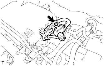
| 22. REMOVE AIR CLEANER CASE SUB-ASSEMBLY |
Disconnect the mass air flow meter connector.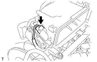
Remove the 3 bolts and remove the air cleaner case sub-assembly.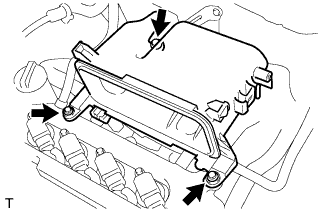
Remove the O-ring from the throttle body assembly.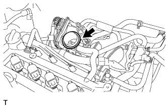
| 23. REMOVE IGNITION COIL ASSEMBLY |
Disconnect the 4 ignition coil assembly connectors.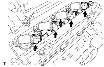
Remove the 4 bolts and 4 ignition coils.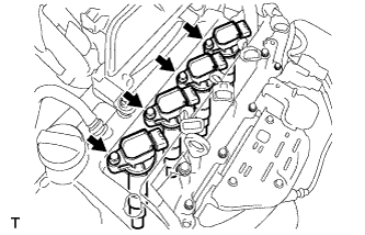
| 24. DISCONNECT VENTILATION HOSE |
Disconnect the ventilation hose from the cylinder head.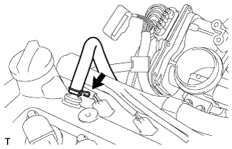
| 25. DISCONNECT NO. 2 VENTILATION HOSE |
Disconnect the No. 2 ventilation hose from the cylinder head.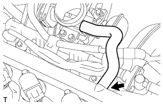
| 26. REMOVE OIL LEVEL GAUGE SUB-ASSEMBLY |
| 27. DISCONNECT ENGINE WIRE (for LHD) |
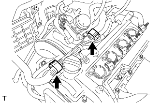 |
Disengage the 2 engine wire harness clamps.
Remove the 2 bolts and disconnect the engine wire harness.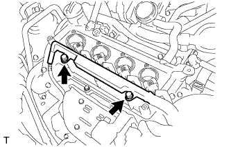
| 28. DISCONNECT ENGINE WIRE (for RHD) |
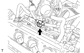 |
Disengage the engine wire harness clamp.
Remove the 2 bolts and disconnect the engine wire harness.
| 29. REMOVE CYLINDER HEAD COVER SUB-ASSEMBLY |
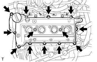 |
Remove the 11 bolts, 2 nuts and 2 seal washers and remove the cylinder head cover.
| 30. DISCONNECT FAN AND GENERATOR V BELT |
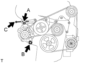 |
Loosen bolts A and B.
Turn adjusting bolt C to release the tension and remove the V belt from the pulleys.
| 31. REMOVE CRANKSHAFT PULLEY |
w/o service hole: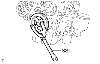
Using SST, hold the crankshaft pulley and loosen the bolt.
- SST
- 09960-10010
(09963-01000, 91651-60855)
w/ service hole: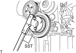
Using SST, hold the crankshaft pulley and loosen the bolt.
- SST
- 09330-00021
09213-54015 (91651-60855)
Remove the bolt and remove the crankshaft pulley.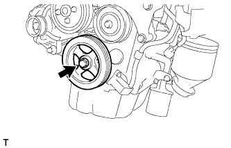
| 32. REMOVE WATER PUMP PULLEY |
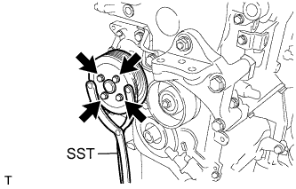 |
Using SST, hold the water pump pulley and remove the 4 bolts.
- SST
- 09960-10010
(09963-00500)
| 33. REMOVE IDLER PULLEY SUB-ASSEMBLY (w/ Air Conditioning System) |
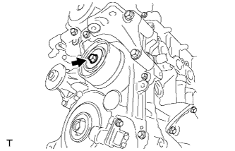 |
Remove the nut and washer and remove the idler pulley.
| 34. REMOVE CRANKSHAFT POSITION SENSOR |
Disconnect the crankshaft position sensor connector.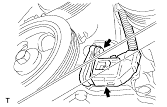
Remove the bolt and remove the crankshaft position sensor.
| 35. REMOVE NO. 2 IDLER PULLEY SUB-ASSEMBLY (w/ Air Conditioning System) |
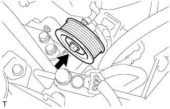 |
Remove the bolt, nut and washer and remove the No. 2 idler pulley.
| 36. REMOVE CAM TIMING OIL CONTROL VALVE ASSEMBLY |
Disconnect the connector.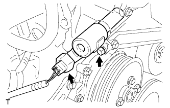
Remove the bolt and remove the cam timing oil control valve assembly.
| 37. REMOVE OIL PAN SUB-ASSEMBLY |
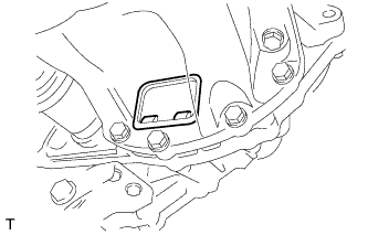 |
Remove the service hole cover.
Remove the 2 nuts and 16 bolts.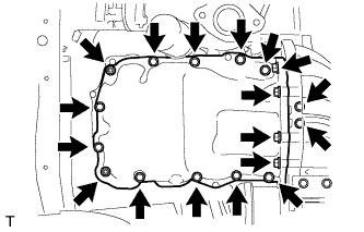
Using a screwdriver with its tip wrapped in protective tape, pry out the oil pan.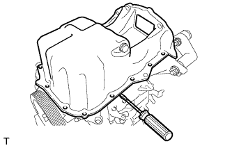
- NOTICE:
- Do not damage the oil pan or the cylinder block.
| 38. REMOVE TRANSVERSE ENGINE ENGINE MOUNTING INSULATOR |
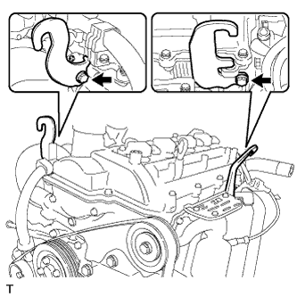 |
Install the bolt and install engine hanger.
Using a chain block, hang up the engine.
Remove the bolt and remove the low pressure pipe bracket of the air conditioner (w/air conditioning).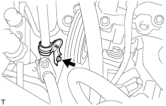
Remove the 5 bolts and nut and remove the engine mounting insulator.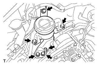
| 39. REMOVE FAN AND GENERATOR V BELT |
Remove the fan and generator V belt.
| 40. REMOVE ENGINE MOUNTING STAY RH |
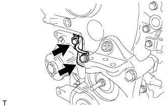 |
Remove the 2 bolts and remove engine mounting stay RH.
| 41. REMOVE TRANSVERSE ENGINE ENGINE MOUNTING BRACKET |
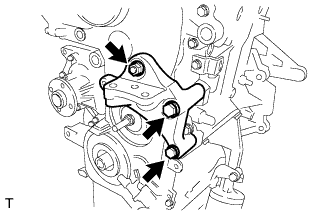 |
Remove the 2 bolts and nut and remove the engine mounting bracket.
| 42. REMOVE TIMING CHAIN OR BELT COVER SUB-ASSEMBLY |
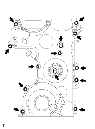 |
Remove the 10 bolts and 2 stud bolts.
Using a screwdriver with its tip wrapped in protective tape, pry out the timing chain cover.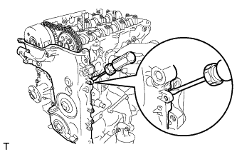
- NOTICE:
- Do not damage the timing chain cover, the cylinder block or the cylinder head.
Remove the gasket.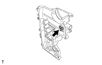
| 43. REMOVE TIMING CHAIN OR BELT COVER OIL SEAL |
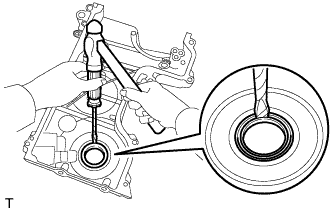 |
Using a screwdriver with its tip wrapped in protective tape, remove the oil seal.
| 44. REMOVE NO. 1 CRANKSHAFT POSITION SENSOR PLATE |
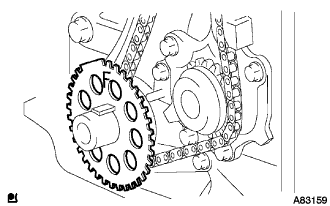 |
Remove the No. 1 crankshaft position sensor plate.
| 45. REMOVE CHAIN TENSIONER PLUNGER |
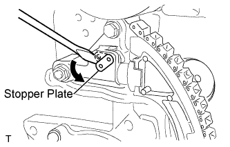 |
Move the stopper plate downward and hold it with its lock released.
- HINT:
- If the lock of the stopper plate is hard to release, using the hexagonal portion of the camshaft, turn the camshaft slightly left and right.
Keep the stopper plate with the plunger pushed to the end of the stopper plate.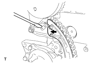
Align the holes in the stopper plate and the chain tensioner plunger.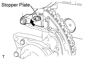
- HINT:
- If it is hard to align the holes in the stopper plate and the chain tensioner plunger, slightly turn the camshaft both ways and align them.
Insert a 3mm diameter bar into the holes in the stopper plate and the chain tensioner plunger.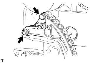
Remove the bolt and the nut and remove the chain tensioner plunger.
| 46. REMOVE TIMING CHAIN TENSION ARM |
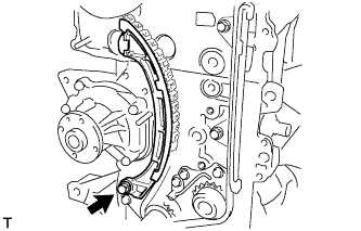 |
Remove the bolt and remove the timing chain tension arm.
| 47. REMOVE TIMING CHAIN GUIDE |
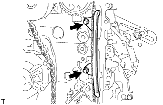 |
Remove the 2 bolts and remove the timing chain guide.
| 48. REMOVE NO. 2 TIMING CHAIN GUIDE |
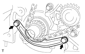 |
Remove the 2 bolts and remove the No. 2 timing chain guide.
| 49. REMOVE CHAIN SUB-ASSEMBLY |
| 50. REMOVE NO. 1 OIL NOZZLE SUB-ASSEMBLY |
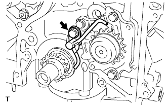 |
Remove the bolt and remove the No. 1 oil nozzle.
| 51. REMOVE OIL PUMP ASSEMBLY |
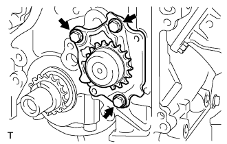 |
Remove the 3 bolts and remove the oil pump.