P0138 Oxygen Sensor Circuit High Voltage (Bank 1 Sensor 2)
Diagnostic trouble codes · Vehicles built from Nov 2005
CAUTION / NOTICE / HINT
- HINT:
- Sensor 2 refers to the sensor mounted behind the Three-Way Catalytic Converter (TWC) and located far from the engine assembly.
DESCRIPTION
Refer to DTC P0136 (Click here).| DTC No. |
DTC Detection Conditions |
Trouble Areas |
| P0138 |
Rear Heated Oxygen (HO2) sensor output voltage 1.2 V or more for 10 seconds (1 trip detection logic) |
|
WIRING DIAGRAM
Refer to DTC P0136 (Click here).CONFIRMATION DRIVING PATTERN
- HINT:
- Performing this confirmation pattern will activate the DTC detection of the ECM. This is very useful for verifying the completion of a repair.
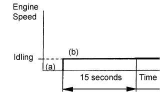

- (a) Clear DTCs (Click here).
- (b) Start the engine and let the engine idle for 15 seconds.
- (c) Read the DTC.
- NOTICE:
- If the conditions in this test are not strictly followed, malfunctions may not be detected.
INSPECTION PROCEDURE
- HINT:
- It is possible that the malfunctioning area can be found using the Active Test Control operation. The Active Test can determine if the heated oxygen sensor or other potential trouble areas are malfunctioning or not.
- The injection volume can be switched to -12.5% (decrease) or +25% (increase) by the Active Test.
- The Active Test procedure enables a technician to check and graph the voltage outputs of the heated oxygen sensors.
- Procedure:
- Connect the intelligent tester to the DLC3.
- Turn the ignition switch on (IG).
- Warm up the engine by running the engine at 2,500 rpm for approximately 90 seconds.
- Select the following menu items: Powertrain / Engine and ECT / Active Test / Control the Injection Volume for A/F Sensor.
- Perform the Active Test while the engine is idling.
- Standard:
- The heated oxygen sensor reacts in accordance with the increases and decreases in injection volume:
+25% → RICH output: More than 0.5 V
-12.5% → LEAN output: Less than 0.4 V
- NOTICE:
- The heated oxygen sensor (sensor 1) has an output delay of a few seconds and the heated oxygen sensor (sensor 2) has a maximum output delay of 20 seconds.
- If the vehicle is short of fuel, the air-fuel ratio becomes LEAN and the DTCs are recorded.
| Case |
Heated Oxygen Sensor Voltage (sensor 1) |
Heated Oxygen Sensor Voltage (sensor 2) |
Main Suspected Trouble Area |
||
| 1 |
Injection Volume +25% -12.5% |
 |
Injection Volume +25% -12.5% |
|
- |
| Heated Oxygen Sensor Voltage 0.5 V or more Below 0.4 V |
 |
Heated Oxygen Sensor Voltage 0.5 V or more Below 0.4 V |
 |
||
| 2 |
Injection Volume +25% -12.5% |
|
Injection Volume +25% -12.5% |
|
|
| Heated Oxygen Sensor Voltage Almost no reaction |
 |
Heated Oxygen Sensor Voltage 0.5 V or more Below 0.4 V |
|
||
| 3 |
Injection Volume +25% -12.5% |
|
Injection Volume +25% -12.5% |
|
|
| Heated Oxygen Sensor Voltage 0.5 V or more Below 0.4 V |
|
Heated Oxygen Sensor Voltage Almost no reaction |
|
||
| 4 |
Injection volume +25% -12.5% |
|
Injection Volume +25% -12.5% |
|
|
| Heated Oxygen Sensor Voltage Almost no reaction |
|
Heated Oxygen Sensor Voltage Almost no reaction |
|
||
- HINT:
- Read freeze frame data using an intelligent tester. Freeze frame data records the engine conditions when a malfunction is detected. When troubleshooting, freeze frame data can help determine if the vehicle was running or stopped, if the engine was warmed up or not, if the air-fuel ratio was LEAN or RICH, and other data from the time the malfunction occurred.
| 1. READ VALUE USING INTELLIGENT TESTER (OUTPUT VOLTAGE OF HEATED OXYGEN SENSOR (SENSOR 2)) |

Connect an intelligent tester to the DLC3.
Turn the ignition switch on (IG) and turn the tester on.
Select the following menu items: Powertrain / Engine and ECT / Data List / O2S B1 S2.
- Result:
Heated Oxygen Sensor (Sensor 2) Voltage
Proceed To
More than 1.2 V
A
Less than 1.0 V
B
|
|
||||

| A | |
 |
| 2. CHECK HARNESS AND CONNECTOR (CHECK FOR SHORT) |
Disconnect the C42 Heated Oxygen (HO2) sensor (sensor 2) connector.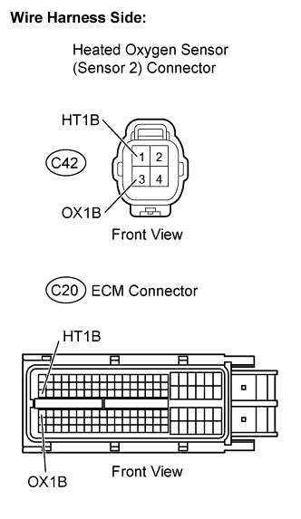
Disconnect the C20 ECM connector.
Check the resistance.
- Standard resistance (Check for short):
Tester Connections
Specified Conditions
HT1B (C20-47) - OX1B (C20-64)
10 kΩ or higher
Reconnect the ECM connector.
Reconnect the HO2 sensor connector.
|
|
||||

| OK | |
|
| 3. INSPECT HEATED OXYGEN SENSOR (CHECK FOR SHORT) |
Disconnect the C42 HO2 sensor (sensor 2) connector.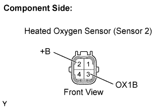
Check the resistance.
- Standard resistance:
Tester Connections
Specified Conditions
OX1B (3) - +B (2)
10 kΩ or higher
Reconnect the HO2 sensor connector.
|
|
||||
| OK | ||
 |
||
| ||
| 4. CHECK WHETHER DTC OUTPUT RECURS (DTC P0138) |
Connect an intelligent tester to the DLC3.
Turn the ignition switch on (IG) and turn the tester on.
Clear DTCs (Click here).
Start the engine.
Allow the engine to idle for 15 seconds or more.
Select the following menu items: Powertrain / Engine and ECT / DTC.
Read DTCs.
- Result:
Display (DTC Output)
Proceed To
P0138
A
No output
B
|
|
||||
| A | ||
|
||
| ||