SYSTEM DESCRIPTION
Troubleshooting · Vehicles built from Nov 2005
| GENERAL |
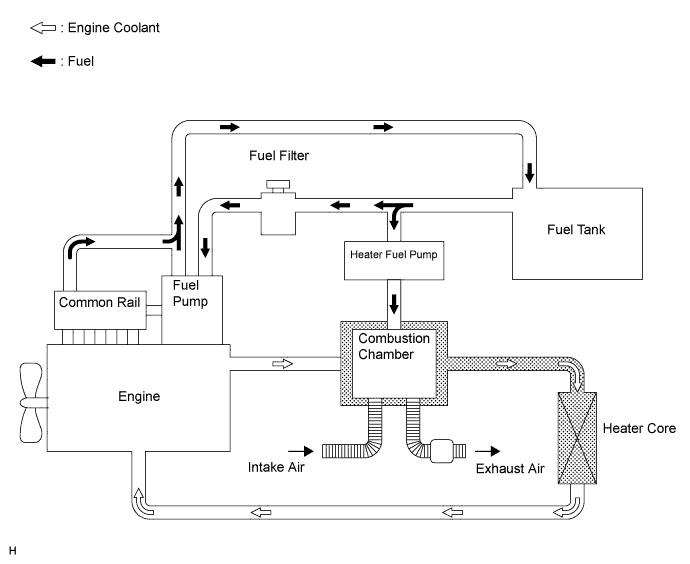
This system burns fuel to enhance the heating effect by heating the water between the engine and the heater core. This system, which consists of a combustion heater assembly, power heater switch and heater fuel pump, operates when the engine is running and the power heater switch is turned on.
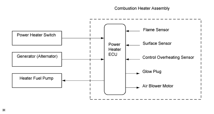
- The combustion heater assembly consists of an ECU, flame sensor, surface sensor, control overheating sensor, glow plug, and air blower motor. It cannot be disassembled.
- The ECU in the combustion heater assembly controls this system in accordance with the signals received from the sensors and switches.
- The combustion heater assembly consists of an ECU, flame sensor, surface sensor, control overheating sensor, glow plug, and air blower motor. It cannot be disassembled.
| SYSTEM DIAGRAM |
System diagram

| WATER AND FUEL CIRCUITS |
Water and fuel circuits