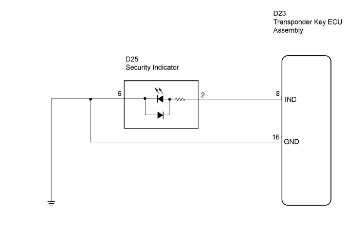
ENGINE IMMOBILISER SYSTEM > Security Indicator Light Circuit |
| 1.PERFORM ACTIVE TEST USING INTELLIGENT TESTER |
Connect the intelligent tester to the DLC3.
Turn the ignition switch on.
Perform the ACTIVE TEST according to the display on the tester.
| Item | Tester Details | Diagnostic Note |
| Security Indic | Turn security indicator ON/OFF | - |
|
| ||||
| NG | |
 |
| 2.CHECK WIRE HARNESS AND CONNECTOR (TRANSPONDER KEY ECU - SECURITY INDICATOR LIGHT) |
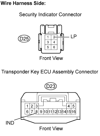 |
Disconnect the D23 transponder key ECU and D25 security indicator connectors.
Measure the resistance.
| Tester Condition | Specified Condition |
| D23-8 (IND) - D25-2 (LP) | Below 1Ω |
| D23-8 (IND) - Body ground | 10 kΩor higher |
Reconnect the transponder key ECU and security indicator connectors.
|
| ||||
| OK | |
|
| 3.INSPECT TRANSPONDER KEY ECU ASSEMBLY |
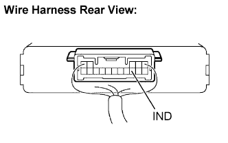 |
Remove the transponder key ECU assembly with its connectors still connected.
Measure the voltage.
| Tester Condition | Condition | Specified Condition |
| D23-8 (IND) - Body ground | Immobiliser set | 11 to 14 V and below 1 V output alternately |
Reinstall the transponder key ECU assembly.
|
| ||||
| OK | ||
 | ||
| ||

