MANUAL TRANSAXLE UNIT > REASSEMBLY |
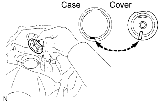
| 1. INSTALL OUTPUT SHAFT COVER |
|
Coat the output shaft cover with MP grease and install it onto the front transaxle case.
| 2. INSTALL OUTPUT SHAFT FRONT BEARING |
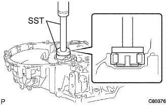 |
Coat a new output shaft front bearing with gear oil. Using SST and a press, install it onto the front transaxle case.
| 3. INSTALL FRONT TRANSAXLE CASE OIL SEAL |
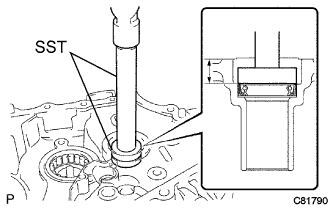 |
Using SST and a hammer, install a new front transaxle case oil seal onto the front transalxe case.
Coat the lip of the front transaxle case oil seal with MP grease.
| 4. INSTALL INPUT SHAFT FRONT BEARING |
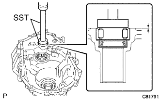 |
Coat a new input shaft front bearing with gear oil, and using SST and a press, install it onto the front transaxle case.
| 5. INSTALL SHIFT AND SELECT LEVER SHAFT NEEDLE ROLLER BEARING |
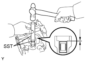 |
Using SST and a hammer, install the shift and select lever shaft needle roller bearing onto the transmission case.
| 6. INSTALL SHIFT AND SELECT LEVER SHAFT OIL SEAL |
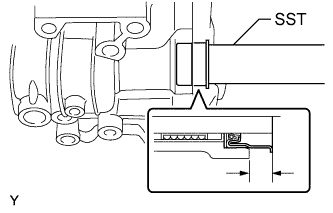 |
Using SST, install the shift and select lever shaft oil seal onto the transmission case.
| 7. INSTALL FR DIFFERENTIAL CASE FRONT TAPERED ROLLER BEARING |
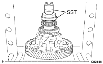 |
Using SST and a press, install the front differential case front tapered roller bearing (inner race) onto the front differential case.
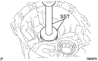 |
Using SST and a press, install the front differential case front tapered roller bearing (outer race) together with the plate washer onto the front transaxle case.
| 8. INSTALL FR DIFFERENTIAL CASE REAR TAPERED ROLLER BEARING |
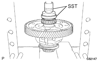 |
Using SST and a press, install the front differential case rear tapered roller bearing (inner race) onto the differential case.
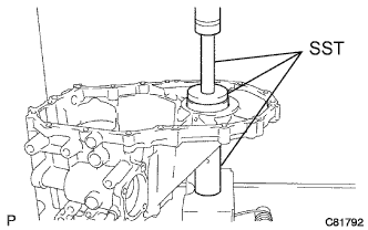 |
Using SST and a press, install the front differential case rear tapered roller bearing (outer race) with plate washer onto the transmission case.
| 9. ADJUST DIFFERENTIAL SIDE BEARING PRELOAD |
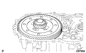 |
Coat the differential case assembly with gear oil, and install it onto the front transaxle case.
Install the manual transmission case with the 16 bolts.
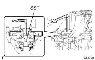 |
Using SST and a torque wrench, turn the differential case assembly to the right and left 2 or 3 times to allow the bearings to settle.
|
Using SST and a torque wrench, measure the preload.
| Mark | Thickness mm (in.) | Mark | Thickness mm (in.) |
| AA | 2.10 (0.0827) | LL | 2.60 (0.1024) |
| BB | 2.15 (0.0846) | MM | 2.65 (0.1043) |
| CC | 2.20 (0.0866) | NN | 2.70 (0.1063) |
| DD | 2.25 (0.0886) | PP | 2.75 (0.1083) |
| EE | 2.30 (0.0906) | QQ | 2.80 (0.1102) |
| FF | 2.35 (0.0925) | RR | 2.85 (0.1122) |
| GG | 2.40 (0.0945) | SS | 2.90 (0.1142) |
| HH | 2.45 (0.0965) | TT | 2.95 (0.1161) |
| JJ | 2.50 (0.0984) | UU | 3.00 (0.1181) |
| KK | 2.55 (0.1004) | - | - |
Remove the 16 bolts and the manual transmission case.
Remove the differential case assembly from the front transaxle case.
| 10. INSTALL TRANSMISSION CASE OIL SEAL |
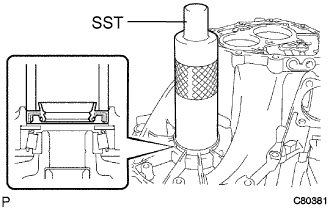 |
Using SST and a hammer, install a new transmission case oil seal onto the manual transmission case.
Coat the lip of the front transmission case oil seal with MP grease.
| 11. INSTALL TRANSAXLE CASE OIL SEAL |
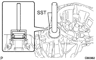 |
Using SST and a hammer, install a new transaxle case oil seal onto the front transaxle case.
Coat the lip of the transaxle case oil seal with MP grease.
| 12. INSTALL TRANSMISSION MAGNET |
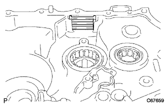 |
Clean the transmission magnet and install it onto the front transaxle case.
| 13. INSTALL BEARING LOCK PLATE |
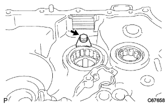 |
Install the bearing lock plate onto the front transaxle case with the bolt.
| 14. INSTALL OIL RECEIVER PIPE NO. 1 |
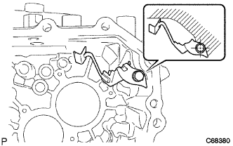 |
Install oil receiver pipe No. 1 onto the manual transmission case with the bolt.
| 15. INSTALL OIL RECEIVER PIPE NO. 2 |
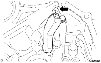 |
Install oil receiver pipe No. 2 onto the manual transmission case with the bolt.
| 16. INSTALL REVERSE RESTRICT PIN ASSEMBLY |
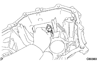 |
Install the reverse restrict pin assembly onto the manual transmission case.
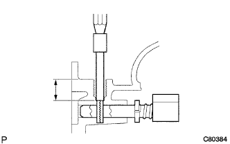 |
Using a pin punch (φ5 mm) and a hammer, install the slotted pin onto the reverse restrict pin assembly.
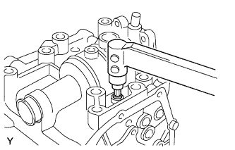 |
Apply adhesive to the reverse restrict pin plug.
Using a hexagon wrench and a torque wrench, install the reverse restrict pin plug onto the manual transmission case.
| 17. INSTALL MANUAL TRANSAXLE CASE RECEIVER |
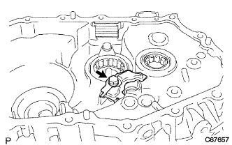 |
Install the manual transaxle case receiver onto the front transaxle case with the bolt.
| 18. INSTALL DIFFERENTIAL CASE ASSEMBLY |
|
Coat the differential case tapered roller bearing with gear oil and install the differential case assembly onto the front transaxle case.
| 19. INSTALL INPUT SHAFT ASSEMBLY |
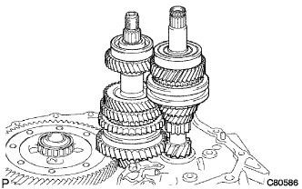 |
Coat the sliding and rotating surfaces of the input and output shafts with gear oil and install them onto the transaxle case.
| 20. INSTALL REVERSE IDLER GEAR SUB-ASSEMBLY |
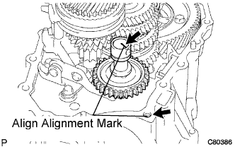 |
Coat the reverse idler gear sub-assembly, thrust washer and reverse idler gear shaft with gear oil and install them as shown in the illustration.
| 21. INSTALL GEAR SHIFT FORK SHAFT NO.1 |
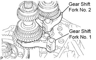 |
Coat gear shift fork No. 1 and gear shift fork No. 2 with gear oil and install them.
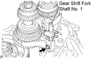 |
Coat gear shift fork shaft No. 1 with gear oil and install it.
Apply adhesive to the shift fork set bolt.
Install the shift fork set bolt.
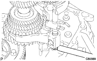 |
Using a brass bar and a hammer, install a new shaft snap ring onto gear shift fork shaft No. 1.
| 22. INSTALL GEAR SHIFT FORK SHAFT NO.3 |
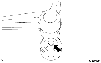 |
Coat the 2 shift fork balls with MP grease and install them onto the reverse shift fork.
Install the reverse shift fork onto gear shift fork shaft No. 3.
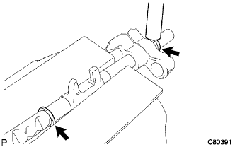 |
Using a brass bar and a hammer, install 2 new shift fork shaft snap rings onto shift fork shaft No. 3.
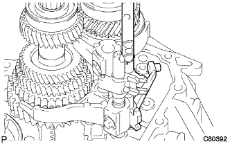 |
Coat gear shift fork shaft No. 3 with gear oil and install it.
| 23. INSTALL GEAR SHIFT FORK SHAFT NO.2 |
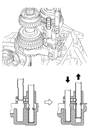 |
Coat gear shift head No. 1 and gear shift fork shaft No. 2 with gear oil and install them.
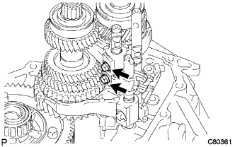 |
Coat the 2 shift lock bolts with adhesive and install them onto gear shift fork No. 2 and shift head No. 1.
| 24. INSTALL REVERSE SHIFT ARM BRACKET ASSEMBLY |
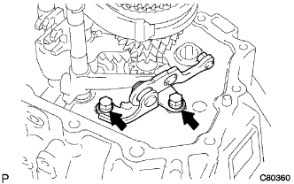 |
Install the reverse shift arm bracket assembly onto the front transaxle case with the 2 bolts.
| 25. INSTALL MANUAL TRANSMISSION CASE |
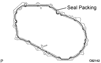 |
Apply seal packing to the manual transmission case, as shown in the illustration.
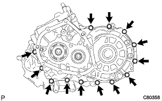 |
Coat the 13 bolts with adhesive and install them onto the manual transmission case.
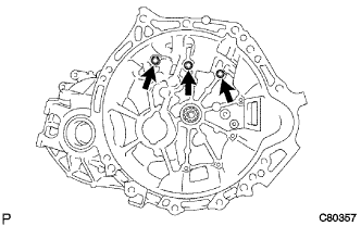 |
Coat the 3 bolts with adhesive, and install them onto the front transaxle case.
| 26. INSTALL REVERSE IDLER GEAR SHAFT BOLT |
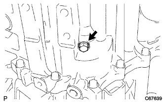 |
Coat the reverse idler gear shaft bolt with adhesive and install it with a new gasket.
| 27. INSTALL LOCK BALL ASSEMBLY NO.2 |
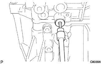 |
Coat lock ball assembly No. 2 with adhesive and install it with a hexagon wrench.
| 28. INSTALL SHIFT DETENT BALL |
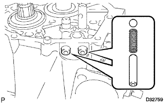 |
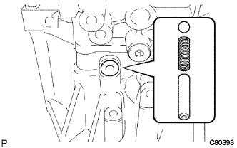
Install the 2 shift detent balls, 2 shift detent ball springs and 2 shift detent ball spring seats No. 1 onto the manual transmission case.
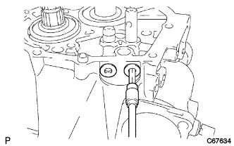 |
Coat the 2 shift detent ball plugs with adhesive and install them using a hexagon wrench.
 |
Install the shift detent ball, shift detent ball compression spring and shift detent ball spring seat No. 1 onto the front transaxle case.
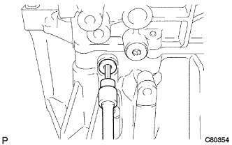 |
Coat the shift detent ball plug with adhesive and install it using a hexagon wrench.
| 29. INSTALL INPUT SHAFT REAR BEARING HOLE SNAP RING |
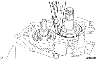 |
Using a snap ring expander, install the input shaft rear bearing hole snap ring onto the input shaft.
| 30. INSTALL OUTPUT SHAFT REAR BEARING HOLE SNAP RING |
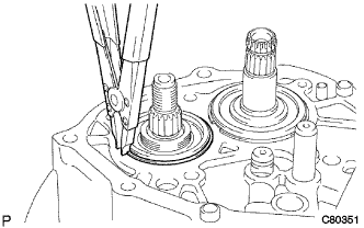 |
Using a snap ring expander, install the output shaft rear bearing hole snap ring onto the output shaft.
| 31. INSTALL SHIFT FORK SHAFT SHAFT SNAP RING |
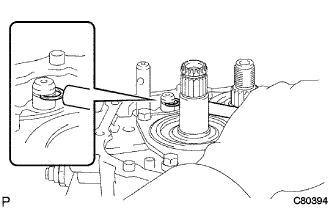 |
Using a brass bar and a hammer, install a new shift fork shaft shaft snap ring onto the shift fork shaft No. 2.
| 32. INSTALL BEARING RETAINER REAR |
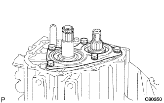 |
Coat the 5 bolts with sealant, and install the bearing retainer rear onto the manual transmission case with the 5 bolts.
| 33. INSTALL 5TH DRIVEN GEAR |
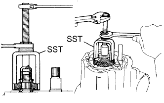 |
Using SST, install the 5th driven gear onto the output shaft.
| 34. INSTALL 5TH GEAR NEEDLE ROLLER BEARING |
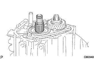 |
Coat the 5th gear needle roller bearing and 5th gear bearing spacer with gear oil, and install them onto the input shaft.
| 35. INSTALL 5TH GEAR |
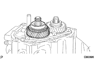 |
Coat the 5th gear with gear oil and install it onto the input shaft.
| 36. INSTALL SYNCHRONIZER RING NO.3 |
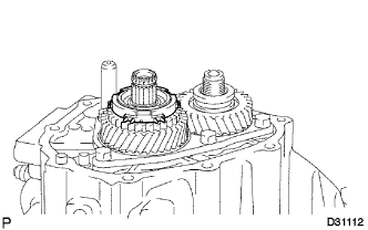 |
Coat synchronizer ring No. 3 with gear oil and install it onto the 5th gear.
| 37. INSTALL TRANSMISSION CLUTCH HUB NO.3 |
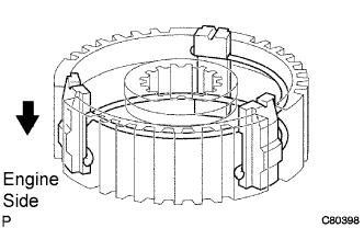 |
Install the 3 synchromesh shifting keys and 2 synchromesh shifting key springs onto transmission clutch hub No. 3, as shown in the illustration.
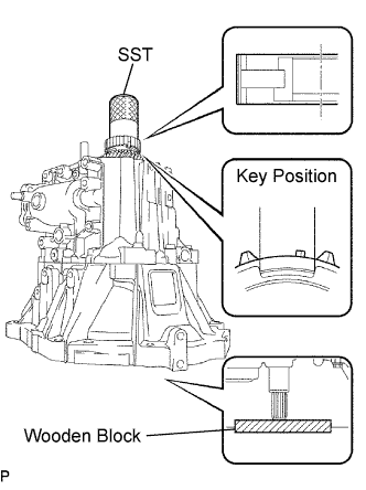 |
Using SST and a hammer, install transmission clutch hub No. 3 onto the input shaft.
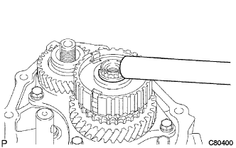 |
Select a clutch hub No. 3 shaft snap ring that will allow minimum axial play.
| Mark | Thickness mm (in.) | Mark | Thickness mm (in.) |
| A | 2.25 (0.0886) | E | 2.49 (0.0980) |
| B | 2.31 (0.0909) | F | 2.55 (0.1004) |
| C | 2.37 (0.0933) | G | 2.61 (0.1028) |
| D | 2.43 (0.0957) | - | - |
Using a brass bar and a hammer, install the snap ring onto the input shaft.
| 38. INSPECT 5TH GEAR THRUST CLEARANCE |
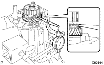 |
Using a dial indicator, measure the 5th gear thrust clearance.
| 39. INSPECT 5TH GEAR RADIAL CLEARANCE |
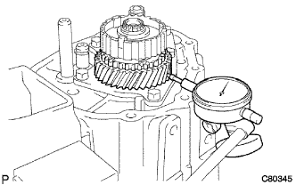 |
Using a dial indicator, measure the 5th gear radial clearance.
| 40. INSTALL GEAR SHIFT FORK NO.3 |
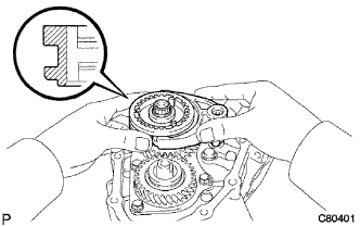 |
Coat transmission clutch hub sleeve No. 3 with gear oil and install it together with gear shift fork No. 3 onto transmission clutch hub No. 3.
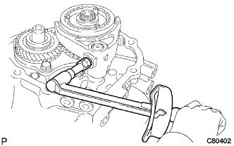 |
Coat the gear shift fork lock bolt with adhesive, and install it onto gear shift fork No. 3.
| 41. INSTALL MANUAL TRANSMISSION OUTPUT SHAFT REAR SET NUT |
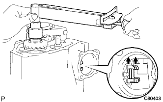 |
Engage the 2 gears simultaneously to lock the transmission.
Coat a new manual transmission output shaft rear set nut with adhesive.
Install the new manual transmission output shaft rear set nut.
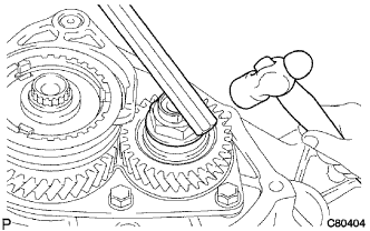 |
Using a chisel and a hammer, stake the manual transmission output shaft rear set nut.
Disengage the 2 gears.
| 42. INSTALL MANUAL TRANSMISSION CASE COVER SUB-ASSEMBLY |
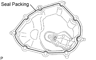 |
Apply seal packing to the manual transaxle case cover sub-assembly as shown in the illustration.
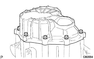 |
Install the manual transmission case cover sub-assembly onto the manual transmission case with the 9 bolts.
| 43. INSTALL SHIFT AND SELECT LEVER SHAFT ASSEMBLY |
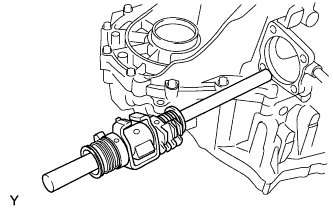 |
Coat the shift and select lever shaft assembly with gear oil, and install it onto the transmission case.
| 44. INSTALL CONTROL SHAFT COVER OIL SEAL |
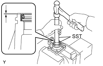 |
Using SST and a hammer, install a new control shaft cover oil seal onto the control shaft cover.
Coat the control shaft cover oil seal with MP grease.
| 45. INSTALL CONTROL SHAFT COVER |
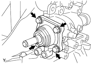 |
Coat the 4 bolts with adhesive. Install a new gasket and control shaft cover onto the manual transmission case with the 4 bolts.
| 46. INSTALL SHIFT GATE PIN |
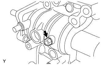 |
Coat the shift gate pin with adhesive.
Install the washer and shift gate pin.
| 47. INSTALL LOCK BALL ASSEMBLY NO.1 |
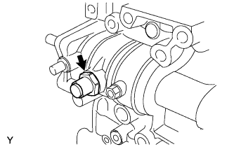 |
Coat lock ball assembly No. 1 with adhesive, install it onto the manual transmission case.
| 48. INSTALL SHIFT LEVER DAMPER |
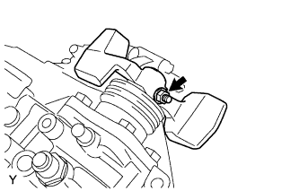 |
Install the dust boot onto the control shaft cover.
Install the shift lever damper with the lock pin onto the shift and select lever shaft assembly.
Install the spring washer with the nut.
| 49. INSTALL FLOOR SHIFT CONTROL SHIFT LEVER |
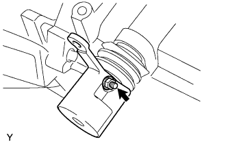 |
Install the dust boot onto the shift and select lever shaft oil seal.
Install the floor shift control shift lever with the lock pin onto the shift and select lever shaft assembly.
Install the spring washer with the nut.
| 50. INSTALL SELECTING BELL CRANK ASSEMBLY |
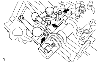 |
Install the selecting bell crank assembly together with the control shift lever bush onto the manual transmission case with the 2 bolts and nut.
| 51. INSTALL BACK-UP LIGHT SWITCH ASSEMBLY |
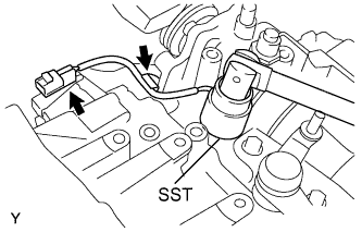 |
Using SST, install the back-up light switch assembly onto the manual transmission case with a new gasket .
Install the back-up light switch wire harness into the 2 clamps.
| 52. INSTALL SPEEDOMETER DRIVEN HOLE COVER SUB-ASSEMBLY |
Install a new O-ring onto the speedometer driven hole cover sub-assembly.
Install the speedometer driven hole cover sub-assembly onto the manual transaxle case with the bolt.
| 53. INSTALL MANUAL TRANSMISSION FILLER PLUG |
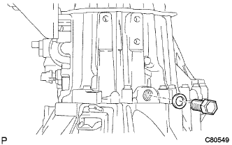 |
Install the manual transmission filler plug onto the manual transmission case with a new gasket.
| 54. INSTALL DRAIN PLUG SUB-ASSEMBLY |
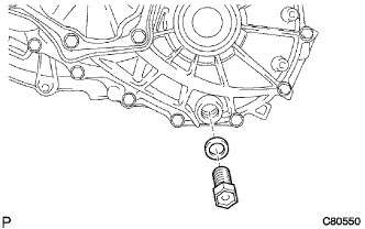 |
Install the drain plug onto the manual transmission case with a new gasket.