 |
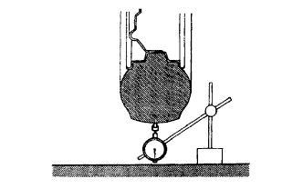
Using a dial indicator, check the tire runout.
- Tire runout:
- 1.4 mm (0.055 in.) or less
FRONT WHEEL ALIGNMENT (for Hatchback) > ADJUSTMENT |
| 1. INSPECT TIRES |
Check the tires for wear and proper inflation pressure.
| Vehicle Model | Tire Size | Vehicle Speed | Front kPa (kgf/cm2, psi) | Rear kPa (kgf/cm2, psi) |
| NCP91R-AGMRKQ NCP91R-AHMRKQ NCP91R-AGPRKQ NCP91R-AHPRKQ NCP90R-AGMRKQ NCP90R-AHMRKQ NCP90R-AGPRKQ NCP90R-AHPRKQ | 175/65R14 82T 185/60R15 84H | Driving below 140 km/h (87 mph) | 220 (2.2, 32) | 220 (2.2, 32) |
| Driving over 140 km/h (87 mph) | 260 (2.7, 38) | 260 (2.7, 38) | ||
| NCP91L-AHMRK NCP91L-AGMRK NCP91L-AGPRK NCP91L-AHPRK NCP90L-AHMRK NCP90L-AGMRK NCP90R-AHMRK NCP90L-AGPRK NCP90L-AHPRK NCP90R-AHPRK | 175/65R14 82T 185/60R15 84H | Driving below 160 km/h (100 mph) | 220 (2.2, 32) | 220 (2.2, 32) |
| Driving over 160 km/h (100 mph) | 230 (2.3, 33) | 230 (2.3, 33) | ||
| NCP91L-AHPRKV NCP90L-AHMRKV NCP90L-AHPRKV | 175/65R14 82T 185/60R15 84H | Driving below 160 km/h (100 mph) | 220 (2.2, 32) | 220 (2.2, 32) |
| Driving over 160 km/h (100 mph) | 230 (2.3, 33) | 230 (2.3, 33) |
|
Using a dial indicator, check the tire runout.
| 2. MEASURE VEHICLE HEIGHT |
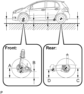 |
| Vehicle Model / Destination | A-B | C-D |
| NCP91R-AGMRKQ NCP91R-AHMRKQ NCP91R-AGPRKQ NCP91R-AHPRKQ NCP90R-AGMRKQ NCP90R-AHMRKQ NCP90R-AGPRKQ NCP90R-AHPRKQ | 88 mm (3.46 in.) | 12 mm (0.47 in.) |
| NCP91L-AHMRK NCP91L-AGMRK NCP91L-AGPRK NCP91L-AHPRK NCP90L-AHMRK NCP90L-AGMRK NCP90R-AHMRK NCP90L-AGPRK NCP90L-AHPRK NCP90R-AHPRK NCP91L-AHPRKV NCP90L-AHMRKV NCP90L-AHPRKV | 86 mm (3.39 in.) | 18 mm (0.71 in.) |
| Rough Road Package | 66 mm (2.60 in.) | -2.0 mm (-0.08 in.) |
| 3. INSPECT WHEEL TURNING ANGLE |
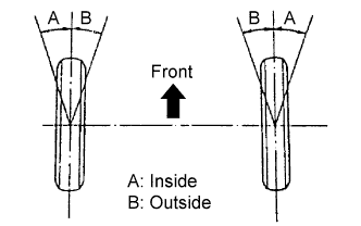 |
Fully turn the steering wheel left and right, and measure the wheel turning angle.
| Vehicle Model / Destination | Tire Size | Inside Wheel | Outside Wheel (Reference) |
| NCP91R-AGMRKQ NCP91R-AHMRKQ NCP91R-AGPRKQ NCP91R-AHPRKQ NCP90R-AGMRKQ NCP90R-AHMRKQ NCP90R-AGPRKQ NCP90R-AHPRKQ | 175/65R14 185/60R15 | 40°57' +/- 2° (40.95° +/- 2°) | 35°17' (35.28°) |
| NCP91L-AHMRK NCP91L-AGMRK NCP91L-AGPRK NCP91L-AHPRK NCP90L-AHMRK NCP90L-AGMRK NCP90R-AHMRK NCP90L-AGPRK NCP90L-AHPRK NCP90R-AHPRK NCP91L-AHPRKV NCP90L-AHMRKV NCP90L-AHPRKV | 165/70R14 | 45°23' +/- 2° (45.38° +/- 2°) | 37°47' (37.78°) |
| 175/65R14 185/60R15 | 41°00' +/- 2° (41.00° +/- 2°) | 35°20' (35.33°) | |
| Rough Road Package | 175/65R14 185/60R15 | 41°23' +/- 2° (41.38° +/- 2°) | 35°48' (35.08°) |
| 4. INSPECT CAMBER, CASTER AND STEERING AXIS INCLINATION |
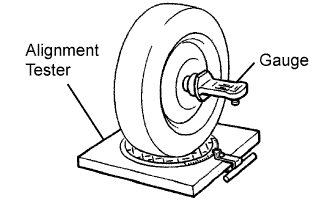 |
Put the front wheel on the center of the alignment tester.
Remove the wheel cap.
Set the camber-caster-steering axis inclination gauge at the center of the axle hub or drive shaft.
Inspect the camber, caster and steering axis inclination.
| Vehicle Model / Destination | Camber | Caster | Steering Axis Inclination (Reference) |
| NCP91R-AGMRKQ NCP91R-AHMRKQ NCP91R-AGPRKQ NCP91R-AHPRKQ NCP90R-AGMRKQ NCP90R-AHMRKQ NCP90R-AGPRKQ NCP90R-AHPRKQ | -0°10' +/- 45' (-0.17° +/- 0.75°) | 4°32' +/- 45' (4.53° +/- 0.75°) | 11°18' (11.30°) |
| NCP91L-AHMRK NCP91L-AGMRK NCP91L-AGPRK NCP91L-AHPRK NCP90L-AHMRK NCP90L-AGMRK NCP90R-AHMRK NCP90L-AGPRK NCP90L-AHPRK NCP90R-AHPRK NCP91L-AHPRKV NCP90L-AHMRKV NCP90L-AHPRKV | -0°08' +/- 45' (-0.13° +/- 0.75°) | 4°44' +/- 45' (4.73° +/- 0.75°) | 11°14' (11.23°) |
| Rough Road Package | 0°08' +/- 45' (0.13° +/- 0.75°) | 4°25' +/- 45' (4.42° +/- 0.75°) | 10°44' (10.73°) |
Remove the camber-caster-steering axis inclination gauge and attachment.
Install the wheel cap.
If the caster and steering axis inclination are not within the specified values after the camber has been correctly adjusted, recheck the suspension parts for damage and wear.
| 5. ADJUST CAMBER |
Remove the front wheel.
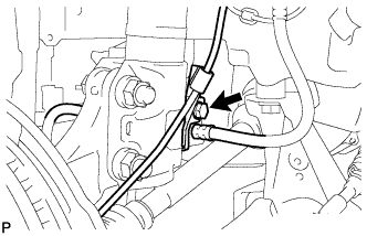 |
Remove the bolt and separate the speed sensor and flexible hose.
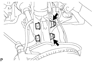 |
Remove the 2 nuts from the lower side of the shock absorber.
Clean the installation surfaces of the shock absorber and steering knuckle.
Provisionally install the 2 nuts (Step A).
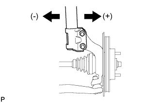 |
Fully push or pull the axle hub in the direction of the required adjustment (Step B).
|
Tighten the 2 nuts.
|
Install the flexible hose and speed sensor with the bolt.
Install the front wheel.
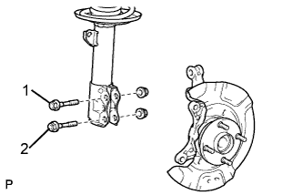 |
Check the camber.
If the measured value is not within the specifications, calculate the required adjustment amount using the formula below.
(Camber adjustment amount) = Center of specified range - Measured value
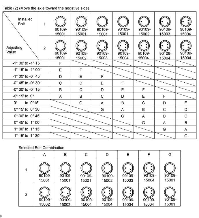
Check the combination of installed bolts. Select appropriate bolts from the table below to adjust the camber to within the specified range.
| Move axle toward (+) in step (B) | Refer to table (1) (Move axle toward positive side) |
| Move axle toward (-) in step (B) | Refer to table (2) (Move axle toward negative side) |
Table (1) (Move the axle toward the positive side)
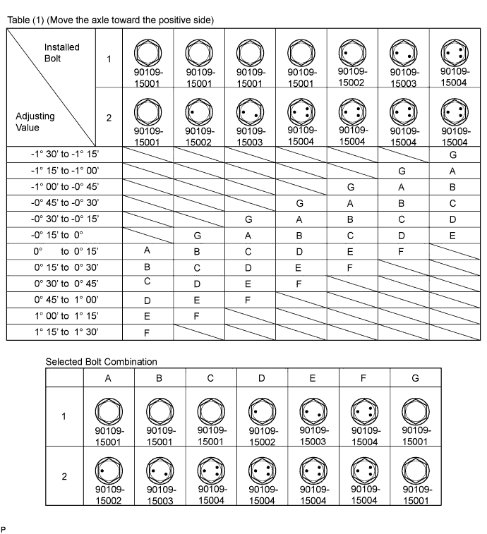
Table (2) (Move the axle toward the negative side).
Repeat the steps mentioned above. At step (A), replace 1 or 2 selected bolts.
| 6. INSPECT TOE-IN |
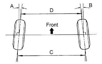 |
| A+B | C-D |
| 0°09' +/- 0°13' (0.15° +/- 0.22°) | 1.5 +/- 2.0 mm (0.06 +/- 0.08 in.) |
| 7. ADJUST TOE-IN |
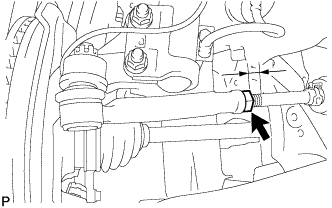 |
Measure the thread lengths of the right and left rack ends.
Remove the rack boot set clips.
Loosen the tie rod end lock nuts.
Adjust the rack ends if the difference in thread length between the right and left rack ends is not within the specified range.
Extend the shorter rack end if the measured toe-in deviates toward the outer-side.
Shorten the longer rack end if the measured toe-in deviates toward the inner-side.
Turn the right and left rack ends by an equal amount to adjust the toe-in.
Make sure that the lengths of the right and left rack ends are the same.
Tighten the tie rod end lock nuts to the specified torque.
Place the boots on the seats.
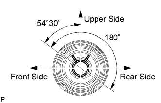 |
Using pliers, install the clip as shown in the illustration.