BRAKE ACTUATOR (for Sedan) > INSTALLATION |
| 1. INSTALL BRAKE ACTUATOR BRACKET ASSEMBLY (for LHD) |
Install the actuator bracket with the 2 nuts.
| 2. INSTALL BRAKE ACTUATOR BRACKET ASSEMBLY (for RHD with VSC) |
|
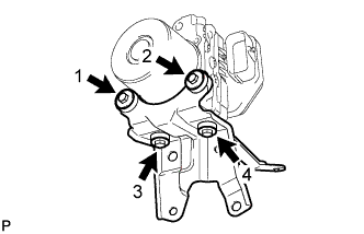
Install the actuator bracket with the 4 bolts in the sequence shown in the illustration.
| 3. INSTALL BRAKE ACTUATOR BRACKET ASSEMBLY (for RHD without VSC) |
Install the actuator bracket with the 2 nuts.
| 4. INSTALL BRAKE ACTUATOR (for LHD) |
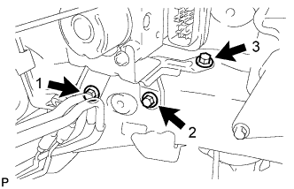 |
Provisionally install the actuator bracket with the 3 bolts in the sequence shown in the illustration.
Tighten the 3 bolts in the sequence shown in the illustration.
Connect a new brake tube clamp.
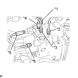 |
Using a union nut wrench (10 mm), install each brake tube into the correct position on the actuator, as shown in the illustration.
| *1 | To Front Wheel RH |
| *2 | To Front Wheel LH |
| *3 | To Rear Wheel RH |
| *4 | To Rear Wheel LH |
| *5 | From Master Cylinder |
| *6 | From Master Cylinder |
Using a union nut wrench (10 mm), install the 2 brake tubes onto the brake master cylinder.
Using a union nut wrench (10 mm), install the 2 brake tubes onto the brake tube No. 1 way.
Using a union nut wrench (10 mm), install the brake tube onto the front flexible hose.
Connect the brake actuator connector.
| 5. INSTALL BRAKE ACTUATOR (for RHD with VSC) |
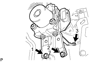 |
Install the brake actuator with bracket with the 3 bolts in the sequence shown in the illustration.
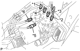 |
Temporarily install each brake tube in the correct positions of the brake actuator as shown in the illustration.
| *1 | To Front Wheel RH |
| *2 | To Front Wheel LH |
| *3 | To Rear Wheel RH |
| *4 | To Rear Wheel LH |
| *5 | From Master Cylinder |
| *6 | From Master Cylinder |
Using a union nut wrench (10 mm), install the 6 brake tubes onto the brake actuator.
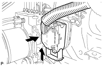 |
Connect the brake actuator connector.
| 6. INSTALL BRAKE ACTUATOR (for RHD without VSC) |
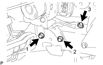 |
Provisionally install the actuator bracket with the 3 bolts in the sequence shown in the illustration.
Tighten the 3 bolts in the sequence shown in the illustration.
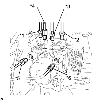 |
Using a union nut wrench (10 mm), install each brake tube into the correct position on the actuator, as shown in the illustration.
| *1 | To Front Wheel RH |
| *2 | To Front Wheel LH |
| *3 | To Rear Wheel RH |
| *4 | To Rear Wheel LH |
| *5 | From Master Cylinder |
| *6 | From Master Cylinder |
Connect the brake actuator connector.
| 7. INSTALL BATTERY CARRIER |
| 8. INSTALL BATTERY TRAY |
| 9. INSTALL BATTERY |
| 10. FILL RESERVOIR WITH BRAKE FLUID |
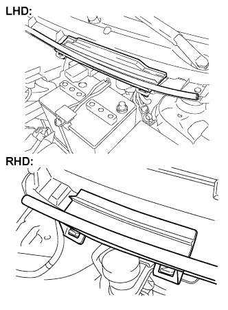 |
Remove the cowl top No. 2 ventilator louver center.
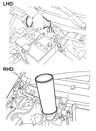 |
Set the brake fluid can upside down on the reservoir.
| 11. BLEED MASTER CYLINDER |
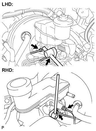 |
Using a union nut wrench (10 mm), disconnect the brake tubes from the master cylinder.
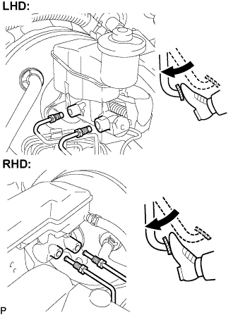 |
Slowly depress the brake pedal and hold it there (Step A).
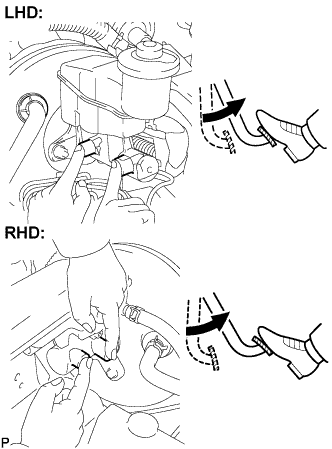 |
Block the outer holes with your fingers, and release the brake pedal (Step B).
Repeat steps A and B 3 or 4 times.
|
Using a union nut wrench (10 mm), connect the brake tubes to the master cylinder.
| 12. BLEED BRAKE LINE |
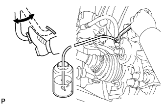 |
Connect the vinyl tube to the bleeder plug.
Depress the brake pedal several times, then loosen the bleeder plug with the pedal depressed (Step C).
At the point where the fluid stops coming out, tighten the bleeder plug, then release the brake pedal (Step D).
Repeat steps C and D until all the air in the fluid is completely bled out.
Tighten the bleeder plug.
Repeat the above procedure to bleed the air out of the brake line for each wheel.
| 13. BLEED BRAKE ACTUATOR (w/ VSC) |
Depress the brake pedal more than 20 times with the engine off.
Connect the intelligent tester to the DLC3, and turn the ignition switch to ON.
Select "Air Bleeding" on the intelligent tester.
Bleed the air out of the brake line when Step 1:
Increase appears on the intelligent tester display.
|
Connect the vinyl tube to either one of the bleeder plugs.
Depress the brake pedal several times, and then loosen the bleeder plug connected to the vinyl tube with the pedal depressed (Step E).
When fluid stops coming out, tighten the bleeder plug and release the brake pedal (Step F).
Repeat Steps E and F until all the air in the fluid is completely bled out.
Tighten the bleeder plug completely.
Repeat the above procedure for each wheel to bleed the air out of the brake line.
Bleed the air out of the suction line when Step 2:
Inhalation appears on the intelligent tester display.
Connect the vinyl tube to the bleeder plug at the right front wheel or the right rear wheel and loosen the bleeder plug.
Operate the brake actuator to bleed the air using the intelligent tester (Step G).
Check if the operation has stopped by referring to the intelligent tester display and tighten the bleeder plug (Step H).
Repeat Steps G and H until all the air in the fluid is completely bled out.
Tighten the bleeder plug.
Repeat the above procedure for the other wheels to bleed the air out of the brake line.
Bleed the air out of the pressure reduction line when Step 3: Decrease appears on the intelligent tester display.
Connect a vinyl tube to either one of the bleeder plugs.
Loosen the bleeder plug (Step I).
Using the intelligent tester, operate the brake actuator assembly, completely depress the brake pedal and hold it there (Step J).
Tighten the bleeder plug, and then release the brake pedal (Step K).
Repeat Steps I to K until all the air in the fluid is completely bled out.
Tighten the bleeder plug.
Repeat the above procedure for the other wheels to bleed the air out of the brake line.
Bleed the air out of the brake line again when Step 4: Increase appears on the intelligent tester display.
|
Connect the vinyl tube to either one of the bleeder plugs.
Depress the brake pedal several times, and then loosen the bleeder plug connected to the vinyl tube with the pedal depressed (Step L).
When fluid stops coming out, tighten the bleeder plug, then release the brake pedal (Step M).
Repeat Steps L and M until all the air in the fluid is completely bled out.
Tighten the bleeder plug.
Repeat the above procedure for the other wheels to bleed the air out of the brake line.
Make sure that the air bleeding is complete by referring to the intelligent tester display and turn off the intelligent tester.
Disconnect the intelligent tester from the DLC3.
Turn the ignition switch off.
| 14. CHECK FLUID LEVEL IN RESERVOIR |
Check the fluid level and add fluid if necessary.
| 15. INSPECTOR FOR BRAKE FLUID LEAK |
| 16. CHECK ACTUATOR WITH INTELLIGENT TESTER |