PARKING BRAKE CABLE (for Sedan) > INSTALLATION |
| 1. INSTALL PARKING BRAKE CABLE |
|
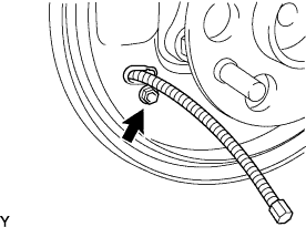
Install the parking brake cable onto the backing plate with the bolt.
Install a new cable clamp B onto the rear axle beam.
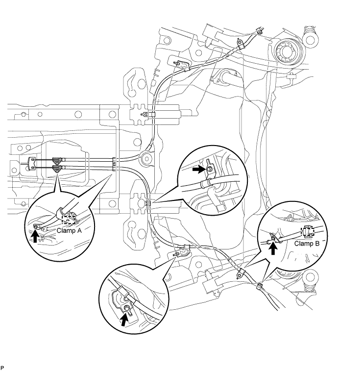
Tighten the 4 bolts.
Pass the parking brake cable through a new cable clamp A, and then install cable clamp A onto the stud bolt.
Connect the cable end to the equalizer.
| 2. INSTALL FUEL TANK COVER VENT CASE SUB-ASSEMBLY (for RH Side) |
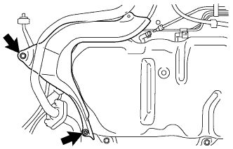 |
Install the fuel tank cover vent case with the bolt and clip
| 3. INSTALL FRONT FLOOR NO. 4 HEAT INSULATOR |
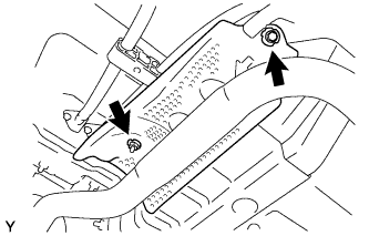 |
Install the heat insulator with the 2 nuts.
| 4. INSTALL REAR BRAKE SHOE KIT |
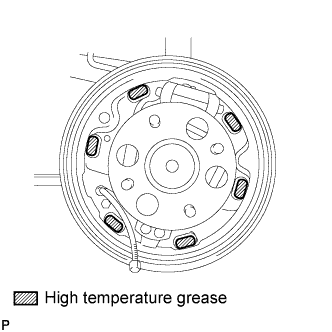 |
Apply high temperature grease to the surface of the backing plate which is in contact with the shoe.
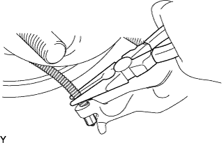 |
Using needle-nose pliers, install the parking brake cable onto the parking brake shoe lever.
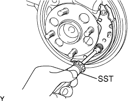 |
Using SST, install the rear brake shoe, pin, shoe hold down spring and shoe hold down spring cup.
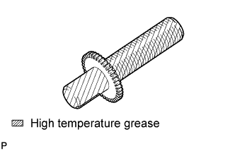 |
Apply high temperature grease to the adjusting bolt.
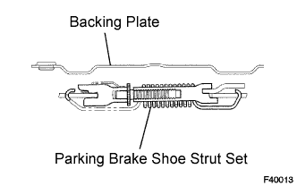 |
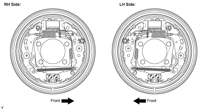
Install the parking brake shoe strut set as shown in the illustration.
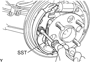 |
Using SST, install the front brake shoe, pin, shoe hold down spring and shoe hold down spring cup.
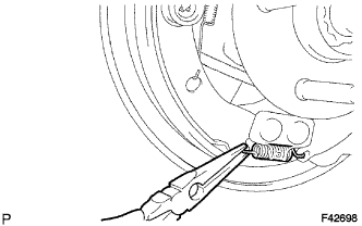 |
Using needle-nose pliers, install the tension spring onto the front brake shoe and rear brake shoe.
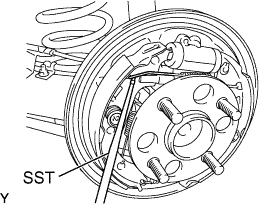 |
Using SST, install the shoe return spring onto the front brake shoe.
| 5. CHECK REAR DRUM BRAKE INSTALLATION |
Check that each part is installed properly.
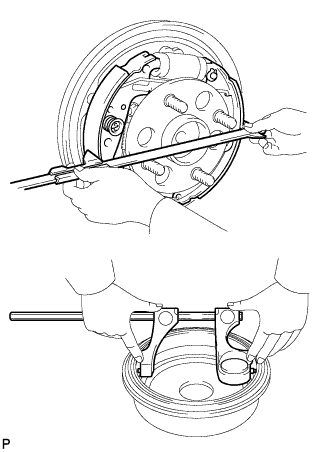 |
Measure the brake drum inner diameter and the diameter of the brake shoes. Check that the difference between the diameters is equal to the specified shoe clearance.
| 6. INSTALL REAR BRAKE DRUM SUB-ASSEMBLY |
| 7. ADJUST REAR DRUM BRAKE SHOE CLEARANCE |
 |
Provisionally install the 2 hub nuts.
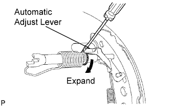
Remove the hole plug, and turn the adjuster to expand the shoe until the drum locks.
Using a screwdriver, release the adjuster 12 notches.
Install the hole plug.
| 8. INSTALL REAR WHEEL |
| 9. INSPECT PARKING BRAKE LEVER TRAVEL |
Slowly pull the parking brake lever to the fully applied position, counting the number of clicks.
| 10. ADJUST PARKING BRAKE LEVER TRAVEL |
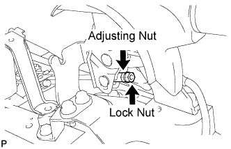 |
Loosen the lock nut and turn the adjusting nut until the parking brake lever travel is corrected to within the specified range.
Tighten the lock nut.
Operate the parking brake lever 3 to 4 times, and check the parking brake lever travel.
Check whether the parking brake drags or not.
When operating the parking brake lever, check that the brake warning light illuminates.
| 11. INSTALL REAR CONSOLE BOX ASSEMBLY |
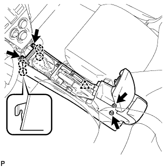 |
Engage the 4 claws and install the rear console box.
Install the 2 bolts and 2 screws.
Connect the clamp.
| 12. INSTALL CONSOLE BOX CARPET |
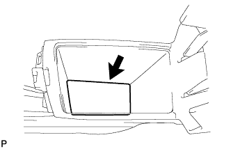 |
Install the console box carpet.
| 13. INSTALL CONSOLE UPPER REAR PANEL SUB-ASSEMBLY |
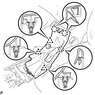 |
Connect the connector.
Engage the 3 clips and 3 claws and install the console upper rear panel.
| 14. INSTALL UPPER CONSOLE PANEL SUB-ASSEMBLY |
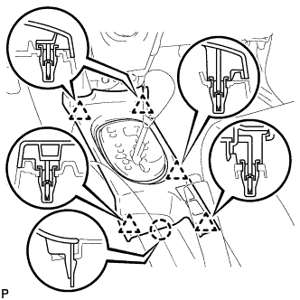 |
Engage the 5 clips and the claw and install the upper console panel.
| 15. INSTALL SHIFT LEVER KNOB SUB-ASSEMBLY (for Manual Transaxle) |
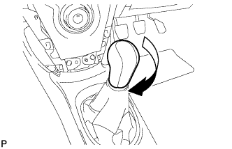 |
Install the shift lever knob.
| 16. INSTALL INSTRUMENT PANEL FINISH PANEL LOWER CENTER |
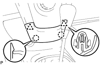 |
Engage the 2 claws and 2 clips and install the instrument panel finish panel lower center.