Home › BODY › ENGINE HOOD / DOOR › BACK DOOR (for Hatchback)

BACK DOOR (for Hatchback) > REASSEMBLY

for Preparation Click here


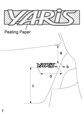
1. INSTALL NO. 2 LUGGAGE COMPARTMENT DOOR NAME PLATE


    B114602E01
  1. Clean the attachment surface.

    1. Using an infrared light, heat the double-sided adhesive tape remaining on the back door panel.

      HINT:
      Heat at 40 to 60°C (104 to 140°F) for 1 to 2 minutes.

    2. Using a shop rag or piece of cloth, rub the remaining double-sided adhesive tape off the back door panel while it is hot from the infrared light.

      NOTICE:
      Installing the No. 2 luggage compartment door name plate while any double-sided tape remains on the back door panel may cause adhesion failure. Therefore, completely remove the double-sided tape.

    3. Using a non-residue solvent, clean the attachment surface.
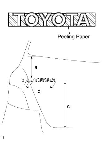
  1. Install a new No. 2 luggage compartment door name plate as shown in the illustration.

    Installation position:
    Mark
    Measurement (along surface)
    a
    158.8 mm (6.252 in.)
    b
    40.3 mm (1.587 in.)
    c
    255.9 mm (10.075 in.)
    d
    157.6 mm (6.205 in.)

    NOTICE:
    Install the No. 2 luggage compartment door name plate in an environment where the ambient temperature is over 20°C (68°F). If it is below 20°C (68°F), using an infrared light, heat the back door panel and the No. 2 luggage compartment door name plate up to 20 to 30°C (68 to 86°F) and install the No. 2 luggage compartment door name plate.


2. INSTALL NO. 1 LUGGAGE COMPARTMENT DOOR NAME PLATE


    B114603E01
  1. Clean the attachment surface.

    1. Using an infrared light, heat the double-sided adhesive tape remaining on the back door panel.

      HINT:
      Heat at 40 to 60°C (104 to 140°F) for 1 to 2 minutes.

    2. Using a shop rag or piece of cloth, rub the remaining double-sided adhesive tape off the back door panel while it is hot from the infrared light.

      NOTICE:
      Installing the No. 1 luggage compartment door name plate while any double-sided tape remains on the back door panel may cause adhesion failure. Therefore, completely remove the double-sided tape.

    3. Using a non-residue solvent, clean the attachment surface.
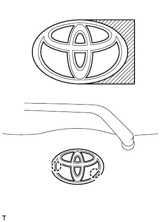
  1. Install a new No. 1 luggage compartment door name plate as shown in the illustration.

    Installation position:
    Mark
    Measurement (along surface)
    a
    158.5 mm (6.24 in.)
    b
    41.7 mm (1.642 in.)
    c
    266.1 mm (10.476 in.)
    d
    156.4 mm (6.157 in.)

    NOTICE:
    Install the No. 1 luggage compartment door name plate in an environment where the ambient temperature is over 20°C (68°F). If it is below 20°C (68°F), using an infrared light, heat the back door panel and the No. 1 luggage compartment door name plate up to 20 to 30°C (68 to 86°F) and install the No. 1 luggage compartment door name plate.


3. INSTALL SYMBOL EMBLEM


    B117713
  1. Clean the attachment surface.

    1. Using an infrared light, heat the double-sided adhesive tape remaining on the back door panel.

      HINT:
      Heat at 40 to 60 °C (104 to 140°F) for 1 to 2 minutes.

    2. Using a shop rag or piece of cloth, rub the remaining double-sided adhesive tape off the back door panel while it is hot from the infrared light.

      NOTICE:
      Installing the symbol emblem while any double-sided tape remains on the back door panel may cause adhesion failure. Therefore, completely remove the double-sided tape.

    3. Using a non-residue solvent, clean the attachment surface.
  1. Insert the 2 bosses into the back door panel and install the symbol emblem.

    NOTICE:
    Install the symbol emblem in an environment where the ambient temperature is over 20°C (68°F). If it is below 20°C (68°F), using an infrared light, heat the back door panel and symbol emblem up to 20 to 30°C (68 to 86°F) and install the symbol emblem.


4. INSTALL BACK DOOR LOCK ACTUATOR ASSEMBLY


B107041
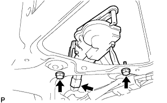
  1. Install the back door lock actuator with the 2 bolts.

    Torque:
    7.0 N*m{ 71 kgf*cm , 62 in.*lbf }

  1. Connect the connector.


5. INSTALL BACK DOOR OUTSIDE HANDLE


B107040
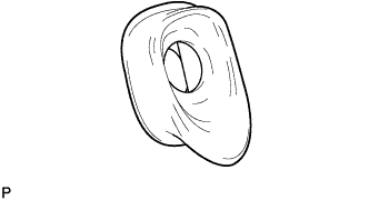
  1. Install the back door outside handle onto the back door panel.


6. INSTALL BACK DOOR LOCK CYLINDER ASSEMBLY


B107039
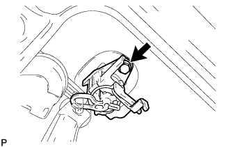
  1. Install the back door lock cylinder with the bolt.

    Torque:
    7.0 N*m{ 71 kgf*cm , 62 in.*lbf }


7. INSTALL BACK DOOR LOCK ASSEMBLY


E113846
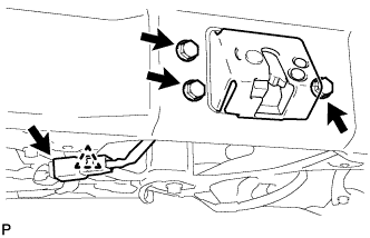
  1. Install the back door lock with the 3 bolts.

    Torque:
    7.5 N*m{ 76 kgf*cm , 66 in.*lbf }

  1. Connect the connector and the clamp.


8. INSTALL BACK DOOR PANEL PROTECTOR NO.2


B127220
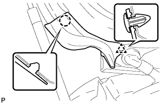
  1. Apply Primer G to the installation part of back door panel protector No. 2.

    NOTICE:
    1. Allow the primer to dry for 3 minutes or more.
    2. Throw away any leftover Primer G.
    3. Do not apply too much Primer G.

  1. Engage the claw and clip and install the protector onto the back door panel, as shown in the illustration.


9. INSTALL BACK DOOR PANEL PROTECTOR NO.1

HINT:
Use the same procedure as described for the No. 2 protector.


10. INSTALL REAR WIPER MOTOR


B210526
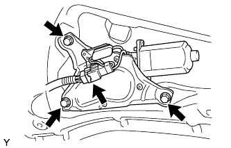
  1. Install the rear wiper motor with the 3 bolts.

    Torque:
    5.5 N*m{ 56 kgf*cm , 49 in.*lbf }

  1. Connect the connector.


11. INSTALL REAR WIPER MOTOR GROMMET


E107901
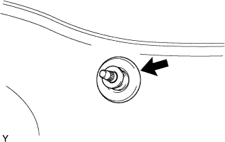
  1. Install the rear wiper motor grommet.


12. INSTALL REAR WIPER ARM AND BLADE ASSEMBLY


E058837E10
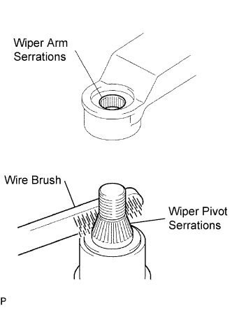
  1. Scrape any metal powder off the serrated part of the wiper arm with a round file or the equivalent (when reinstalling).

  1. Clean the wiper pivot serrations with a wire brush.

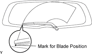
  1. Operate the wiper, then stop the windshield wiper motor in the automatic stop position.


    E107904E01
  1. Install the rear wiper arm into the position shown in the illustration with the nut.

    Torque:
    5.5 N*m{ 56 kgf*cm , 49 in.*lbf }

    HINT:
    Hold the arm hinge down by hand while tightening the nut.


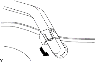
    E107903
  1. Close the rear wiper arm head cap.


13. INSTALL BACK DOOR TRIM BOARD ASSEMBLY


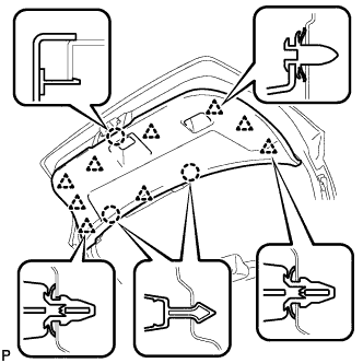
B118076
  1. Engage the 3 claws and 9 clips and install the back door trim board.


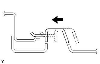
    B104995
  1. Slide the handle plate of the back door trim board to engage it.


14. INSTALL HIGH MOUNTED STOP LIGHT ASSEMBLY


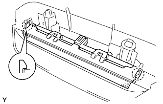
E114438
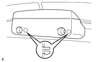
  1. Engage the 2 claws and install the high mounted stop light.


15. INSTALL CENTER STOP LIGHT COVER


E114437
  1. Connect the connector.

  1. Engage the 2 claws.


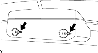
    E107943
  1. Install the center stop light cover with the 2 screws.

    NOTICE:
    When reusing the center stop light cover, replace the screws with 90159-60303 screws to avoid insecure installation.


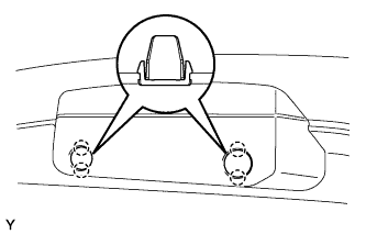
    E114439
  1. Engage the 4 claws and install the rear light cover.