BRAKE PEDAL SUPPORT (for Sedan) > REMOVAL |
| 1. DISCONNECT CABLE FROM NEGATIVE BATTERY TERMINAL |
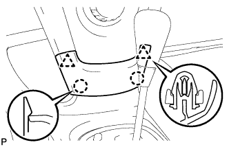
| 2. REMOVE INSTRUMENT PANEL FINISH PANEL LOWER CENTER |
|
Disengage the 2 claws and 2 clips and remove the instrument panel finish panel lower center.
| 3. REMOVE INSTRUMENT PANEL FINISH PANEL END LH |
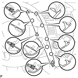 |
Disengage the 6 claws and 3 clips and remove the instrument panel finish panel end LH.
| 4. REMOVE INSTRUMENT PANEL FINISH PANEL END RH |
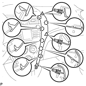 |
Disengage the 6 claws and 3 clips and remove the instrument panel finish panel end RH.
| 5. REMOVE INSTRUMENT CLUSTER FINISH PANEL NO.1 |
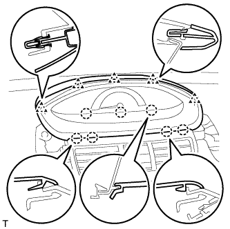 |
Disengage the 4 claws and 5 clips and remove the instrument cluster finish panel.
| 6. REMOVE COMBINATION METER ASSEMBLY |
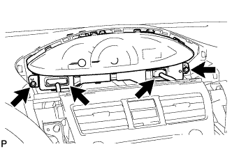 |
Disconnect the 2 connectors.
Remove the 2 screws and pull the combination meter rearward to remove it.
| 7. SEPARATE FRONT DOOR OPENING TRIM WEATHERSTRIP RH |
Separate the front door opening trim weatherstrip.
| 8. SEPARATE FRONT DOOR OPENING TRIM WEATHERSTRIP LH |
Separate the front door opening trim weatherstrip.
| 9. REMOVE FRONT PILLAR GARNISH RH |
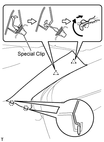 |
w/ Curtain Shield Airbag:
Disengage the 2 clips and the 2 claws and remove the front pillar garnish.
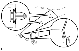 |
w/o Curtain Shield Airbag:
Disengage the 2 clips and the 2 claws and remove the front pillar garnish.
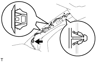 |
Disconnect the antenna connector.
Using a clip remover, remove the 3 clamps.
 |
w/ Curtain Shield Airbag:
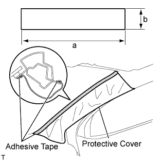
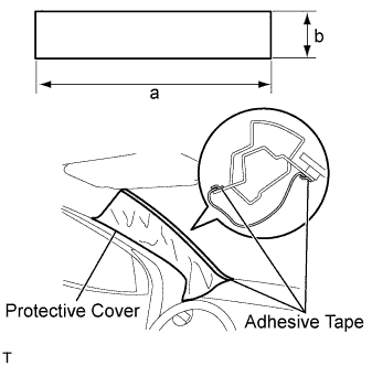
Completely cover the curtain shield airbag with a piece of cloth or nylon and fix the ends of the fabric with adhesive tape, as shown in the illustration.
| Area | Measurement |
| a | 700 mm (27.56 in.) |
| b | 120 mm (4.72 in.) |
| 10. REMOVE FRONT PILLAR GARNISH LH |
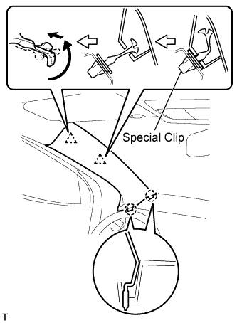 |
w/ Curtain Shield Airbag:
Disengage the 2 clips and the 2 claws and remove the front pillar garnish.
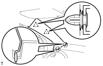 |
w/o Curtain Shield Airbag:
Disengage the 2 clips and the 2 claws and remove the front pillar garnish.
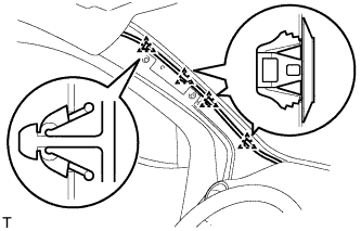 |
Using a clip remover, remove the 4 clamps.
 |
w/ Curtain Shield Airbag:
Completely cover the curtain shield airbag with a piece of cloth or nylon and fix the ends of the fabric with adhesive tape, as shown in the illustration.
| Area | Measurement |
| a | 700 mm (27.56 in.) |
| b | 120 mm (4.72 in.) |
| 11. REMOVE GLOVE COMPARTMENT DOOR ASSEMBLY |
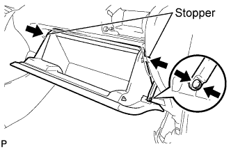 |
Disengage the claw and separate the glove compartment door stopper from the glove compartment door.
Slightly flex the upper part of the glove compartment door assembly to release the 2 stoppers and open the glove compartment door until it becomes horizontal.
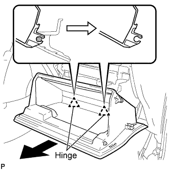 |
Pull the glove compartment door assembly out horizontally to disengage the hinge portion and remove the glove compartment door.
| 12. REMOVE UPPER INSTRUMENT PANEL SUB-ASSEMBLY |
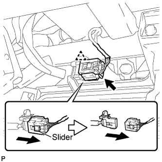 |
Slide the slider and disconnect the passenger airbag connector.
Disconnect the clamp.
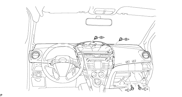
Remove the 2 <C> bolts and 2 <B> screws.
Disengage the 7 clips by lifting the rear side of the instrument panel up.
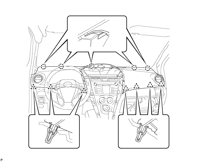
While lifting the instrument panel, slide it toward the rear of the vehicle. Disengage the 5 claws from the front side of the instrument panel and remove the instrument panel.
| 13. REMOVE INSTRUMENT PANEL UNDER TRAY |
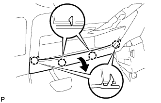 |
Disengage the 4 claws and open the instrument panel under tray.
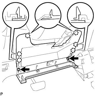 |
Remove the 2 <A> screws.
Disengage the 6 claws and remove the instrument panel under tray.
| 14. REMOVE COLUMN HOLE COVER SILENCER SHEET |
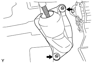 |
Remove the floor carpet and 2 clips and remove the column hole cover silencer.
| 15. REMOVE NO. 2 STEERING INTERMEDIATE SHAFT ASSEMBLY |
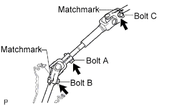 |
Loosen bolt A.
Place matchmarks on the steering intermediate assembly and steering gear assembly.
Remove bolt B and detach the steering intermediate assembly from the steering gear assembly.
Place matchmarks on the steering intermediate assembly and steering column assembly.
Remove bolt C and detach the steering intermediate shaft assembly from the steering column assembly.
| 16. REMOVE STOP LIGHT SWITCH |
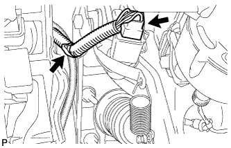 |
Disconnect the connector from the stop light switch.
Disconnect the wire harness clamp from the pedal support.
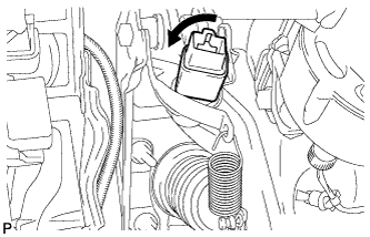 |
Turn the stop light switch counterclockwise, and remove the stop light switch.
| 17. REMOVE STOP LIGHT SWITCH MOUNTING ADJUSTER |
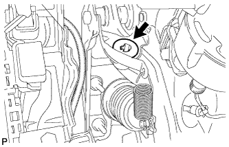 |
Remove the stop light switch mounting adjuster from the pedal support.
| 18. SEPARATE BRAKE MASTER CYLINDER PUSH ROD CLEVIS |
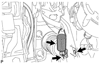 |
Remove the brake pedal return spring.
Remove the clip and the push rod pin and separate the push rod clevis from the brake pedal.
| 19. REMOVE BRAKE PEDAL SUPPORT |
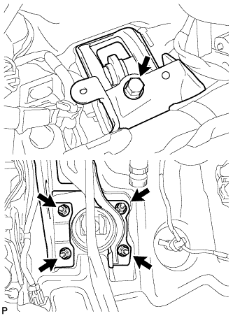 |
Remove the 4 nuts and bolt and remove the pedal support.
| 20. REMOVE BRAKE PEDAL |
Remove the nut and brake pedal shaft and remove the brake pedal from the pedal support.
| 21. REMOVE BRAKE PEDAL BUSH |
Remove the 2 brake pedal bushes from the brake pedal.
| 22. REMOVE BRAKE PEDAL PAD |
Remove the brake pedal pad from the brake pedal.