EMISSION CONTROL SYSTEM > ON-VEHICLE INSPECTION |
| 1. INSPECT FUEL CUT-OFF RPM |
Start and warm up the engine.
Increase the engine speed to approximately 3,500 rpm.
Using a sound scope, check the operation sound of the injector.
Release the throttle lever. Check that the operation noise stops momentarily and then resumes.
| 2. VISUALLY INSPECT HOSES, CONNECTIONS AND GASKETS |
|
Check that there are no cracks, leakage or scratches on the hoses, connections and gaskets.
| 3. INSPECT VARIABLE RESISTOR (for Leaded Gasoline Specification Vehicle) |
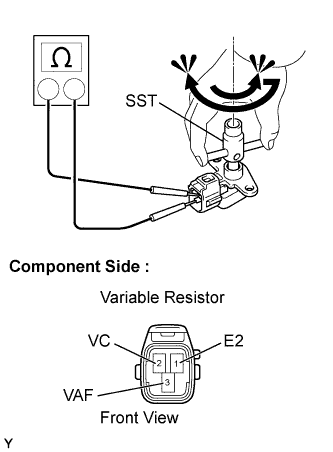 |
Remove the variable resistor.
Measure the resistance between terminals 1 (E2) and 2 (VC) of the variable resistor.
| Tester Connection | Specified Condition |
| E2 - VC | 3.5 to 6.5 kΩ |
Place matchmarks on the variable resistor.
Measure the resistance between terminals 1 (E2) and 3 (VAF) while turning the idle mixture adjusting screw fully clockwise and counterclockwise using SST.
Align the matchmarks on the variable resistor.
Install the variable resistor.
| 4. CHECK CO/HC (for Leaded Gasoline Specification Vehicle) |
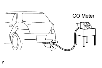 |
Warm up the engine to normal operating temperature.
Turn off all the accessories.
Connect all vacuum lines properly.
Shift the transmission to the N position.
Connect the tachometer.
Accurately measure the ignition timing.
Accurately check the idling speed.
Check that the CO meter is properly calibrated.
Race the engine at 2500 rpm for approximately 2 minutes.
Insert a tester probe at least 40 cm (1.3 ft) into the tail pipe.
Measure the concentration after racing the engine for 1 to 3 minutes to allow the concentration to stabilize.
| 5. INSPECT ECM (for Leaded Gasoline Specification Vehicle) |
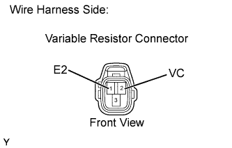 |
Disconnect the variable resistor connector.
Turn the ignition switch on (IG).
Measure the voltage between the terminals of the variable resistor.
| Tester Connection | Specified Condition |
| E2 - VC | 4.5 to 5.5 V |
Reconnect the variable resistor connector.