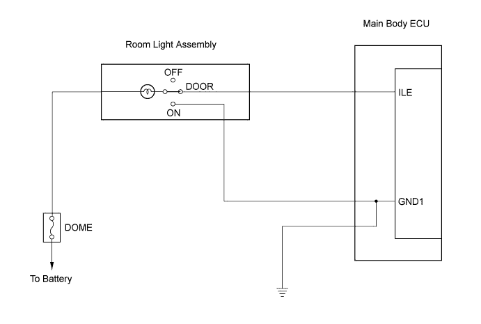
LIGHTING SYSTEM > Illumination Circuit |
| 1.INSPECT FUSE (DOME) |
Remove the DOME fuse from the engine room relay block.
Measure the resistance.
Reinstall the DOME fuse.
|
| ||||
| OK | |
 |
| 2.INSPECT ROOM LIGHT ASSEMBLY |
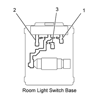 |
Inspect room light assembly.
Remove the room light assembly.
Measure the resistance.
| Tester connection | Switch operation | Specified resistance |
| 1 - 2 1 - 3 | OFF | 10 kΩor higher |
| 1 - 2 | DOOR | Below 1Ω |
| 1 - 3 | ON | Below 1Ω |
Connect the positive (+) lead from the battery to terminal 1 and the negative (-) lead to terminal 2, then check that the light comes on when the switch is in the DOOR position.
Connect the positive (+) lead from the battery to terminal 1 and the negative (-) lead to terminal 3, then check that the light comes on when the switch is in the ON position.
|
| ||||
| OK | |
|
| 3.CHECK HARNESS AND CONNECTOR (BATTERY - ROOM LIGHT ASSEMBLY AND MAIN BODY ECU) |
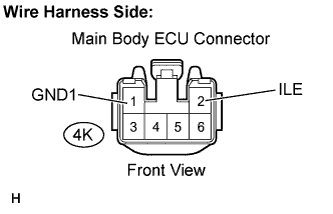 |
Disconnect the 4K main body ECU connector.
Measure the voltage.
| Tester Connection | Condition | Specified Condition |
| 4K-2 (ILE) - Body ground | Room light switch is in the DOOR position | 10 to 14 V |
| 4K-1 (GND1)- Body ground | Room light switch is in the ON position | 10 to 14 V |
Reconnect the main body ECU connector.
|
| ||||
| OK | ||
 | ||
| ||
