CYLINDER HEAD > REMOVAL |
| 1. DISCHARGE FUEL SYSTEM PRESSURE |
| 2. DISCONNECT CABLE FROM NEGATIVE BATTERY TERMINAL |
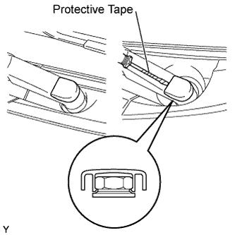
| 3. REMOVE FRONT WIPER ARM HEAD CAP (for Hatchback) |
|
Using a screwdriver with its tip wrapped in protective tape, disengage the claw and remove the 2 front wiper arm head caps.
| 4. REMOVE FRONT WIPER ARM HEAD CAP (for Sedan) |
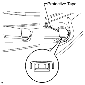 |
Using a screwdriver with its tip wrapped in protective tape, disengage the claw and remove the 2 front wiper arm head caps.
| 5. REMOVE FRONT WIPER ARM AND BLADE ASSEMBLY LH (for Hatchback) |
Operate the wiper, then stop the windshield wiper motor in the automatic stop position.
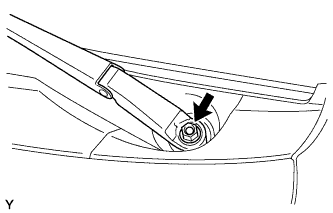 |
Remove the nut and front wiper arm.
| 6. REMOVE FRONT WIPER ARM AND BLADE ASSEMBLY LH (for Sedan) |
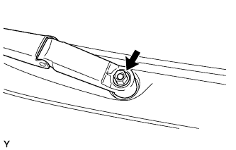 |
Operate the wiper, then stop the windshield wiper motor in the automatic stop position.
Remove the nut and front wiper arm.
| 7. REMOVE FRONT WIPER ARM AND BLADE ASSEMBLY RH (for Hatchback) |
| 8. REMOVE FRONT WIPER ARM AND BLADE ASSEMBLY RH (for Sedan) |
| 9. REMOVE HOOD TO COWL TOP SEAL (for Hatchback) |
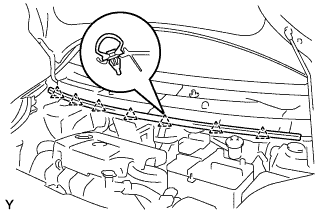 |
Disengage the 7 clips and remove the hood to cowl top seal.
| 10. REMOVE COWL SIDE VENTILATOR SUB-ASSEMBLY LH (for Sedan) |
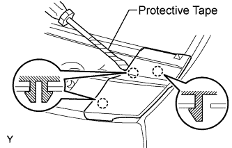 |
Using a screwdriver with its tip wrapped in protective tape, disengage the 3 claws and remove the cowl side ventilator sub-assembly LH.
| 11. REMOVE COWL SIDE VENTILATOR SUB-ASSEMBLY RH (for Sedan) |
| 12. REMOVE COWL TOP VENTILATOR LOUVER SUB-ASSEMBLY (for Hatchback LHD) |
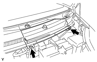 |
Disengage the 2 hooks and remove cowl top ventilator louver center No. 1.
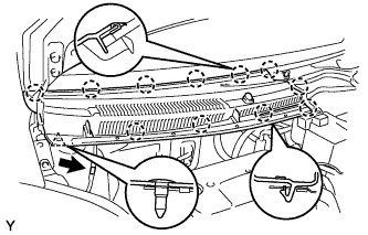 |
Disconnect the washer hose.
Disengage the 11 claws and clip.
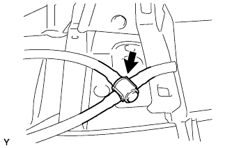 |
Disconnect the washer hose and remove the cowl top ventilator louver sub-assembly.
| 13. REMOVE COWL TOP VENTILATOR LOUVER LH (for Hatchback LHD) |
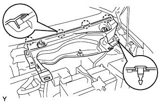 |
Remove the 2 clips.
Disengage the 4 claws and remove the cowl top ventilator louver LH.
| 14. REMOVE COWL TOP VENTILATOR LOUVER SUB-ASSEMBLY (for Hatchback RHD) |
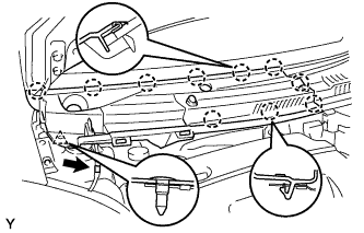 |
Disconnect the washer hose.
Disengage the 10 claws and clip and remove the cowl top ventilator louver sub-assembly.
| 15. REMOVE COWL TOP VENTILATOR LOUVER LH (for Hatchback RHD) |
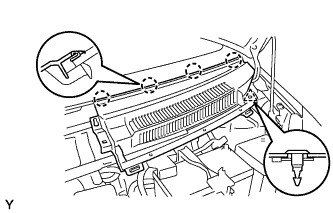 |
Remove the clip.
Disengage the 4 claws and remove the cowl top ventilator louver LH.
| 16. REMOVE COWL TOP VENTILATOR LOUVER SUB-ASSEMBLY (for Sedan RHD) |
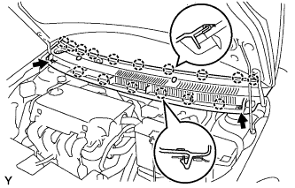 |
Disengage the 2 clips, the 6 claws and the 10 hooks.
Remove the cowl top ventilator louver sub-assembly.
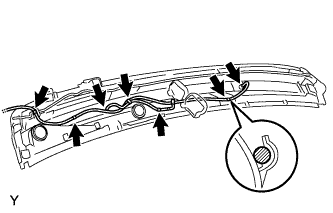 |
Disconnect the washer hoses.
Disengage the 5 hooks.
| 17. REMOVE COWL TOP VENTILATOR LOUVER SUB-ASSEMBLY (for Sedan LHD) |
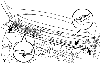 |
Disengage the 3 clips, the 4 claws and the 8 hooks.
Remove the cowl top ventilator louver sub-assembly.
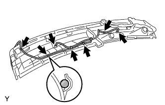 |
Disconnect the washer hoses.
Disengage the 5 hooks.
| 18. REMOVE FRONT WIPER MOTOR AND LINK (for Hatchback) |
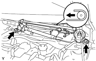 |
Remove the 2 bolts.
Slide the wiper link. Disengage the meshing of the rubber pin, then disconnect the connector and remove the front wiper motor and link.
| 19. REMOVE FRONT WIPER MOTOR AND LINK (for Sedan) |
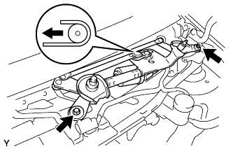 |
Remove the 2 bolts.
Slide the wiper link. Disengage the meshing of the rubber pin, then disconnect the connector and remove the front wiper motor and link.
| 20. REMOVE COWL TO REGISTER DUCT SUB-ASSEMBLY NO. 2 (for Hatchback) |
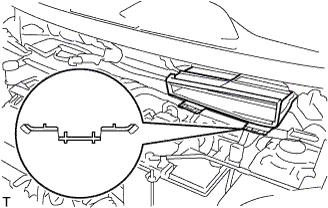 |
Disengage the claw and remove cowl to register duct sub-assembly No. 2.
| 21. REMOVE FRONT AIR SHUTTER SEAL RH (for Sedan) |
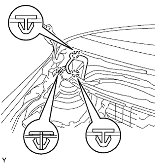 |
Disengage the 3 claws and remove the front air shutter seal.
| 22. REMOVE COWL TOP PANEL OUTER (for Hatchback) |
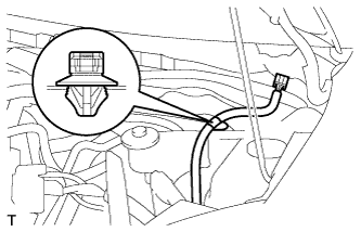 |
Disengage the wire harness clamp.
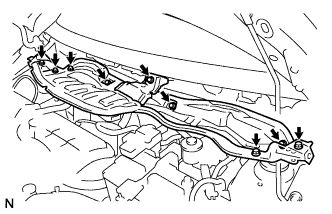 |
Remove the 9 bolts and remove the cowl top panel outer.
| 23. REMOVE COWL TOP PANEL OUTER (for Sedan) |
| 24. REMOVE BATTERY |
| 25. REMOVE BATTERY TRAY |
| 26. REMOVE FRONT WHEEL RH |
| 27. REMOVE ENGINE UNDER COVER RH |
| 28. REMOVE ENGINE UNDER COVER SUB-ASSEMBLY (for Rough Road Area Specification Vehicles) |
| 29. DRAIN ENGINE OIL |
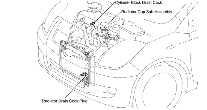
| 30. DRAIN ENGINE COOLANT |
Loosen the radiator drain cock plug.
Remove the radiator cap sub-assembly.
Loosen the cylinder block drain cock plug, then drain the coolant.
| 31. REMOVE CYLINDER HEAD COVER NO. 2 |
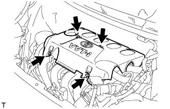 |
Remove the 4 nuts and cylinder head cover No. 2.
| 32. REMOVE AIR CLEANER CAP SUB-ASSEMBLY WITH AIR CLEANER HOSE NO. 1 |
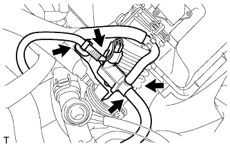 |
Disconnect fuel vapor feed hose No. 1 and fuel vapor feed hose No. 2 from the vacuum switching valve assembly.
Disconnect the vacuum switching valve assembly connector and wire harness clamp.
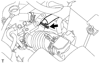 |
Disconnect ventilation hose No. 2.
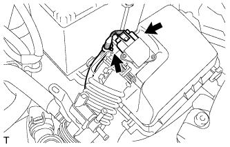 |
Disconnect the wire harness clamp and mass air flow meter connector.
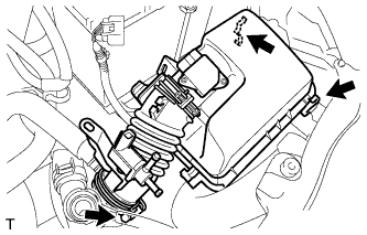 |
Loosen the hose clamp, unlock the air cleaner assembly clamp and remove air cleaner cap sub-assembly with air cleaner hose No. 1.
| 33. DISCONNECT RADIATOR HOSE NO. 3 |
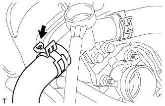 |
Disconnect radiator hose No. 3.
| 34. DISCONNECT RESERVE TANK HOSE |
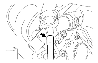 |
Disconnect the reserve tank hose.
| 35. REMOVE WATER FILLER SUB-ASSEMBLY |
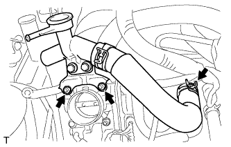 |
Separate radiator hose No. 1 from the cylinder head.
Remove the 2 nuts and remove the water filler sub-assembly.
| 36. DISCONNECT WATER BY-PASS HOSE NO. 2 |
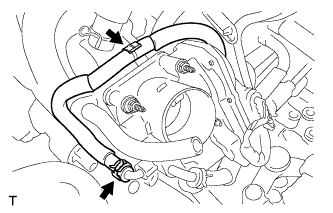 |
Disconnect water by-pass hose No. 2.
| 37. DISCONNECT WATER BY-PASS HOSE |
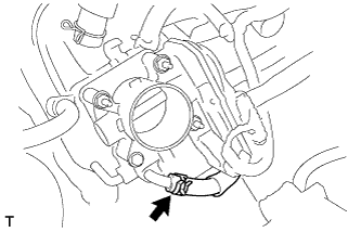 |
Disconnect the water by-pass hose.
| 38. DISCONNECT THROTTLE WITH MOTOR BODY CONNECTOR |
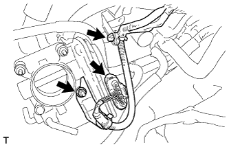 |
Separate the wire harness clamp.
Remove the nut and separate the throttle with motor body connector.
| 39. DISCONNECT VENTILATION HOSE |
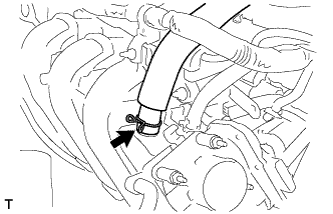 |
Disconnect the ventilation hose.
| 40. DISCONNECT UNION TO CONNECTOR TUBE HOSE |
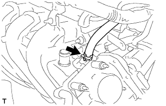 |
Disconnect the union to connector tube hose.
| 41. REMOVE OIL LEVEL GAUGE SUB-ASSEMBLY |
| 42. REMOVE INTAKE MANIFOLD |
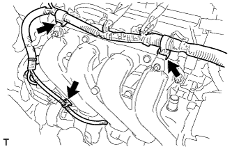 |
Separate the wire harness clamps shown in the illustration.
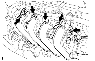 |
Remove the 3 bolts and 2 nuts and remove the intake manifold.
| 43. REMOVE OIL LEVEL GAUGE GUIDE |
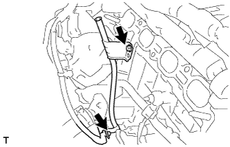 |
Remove the wire harness clamp and the bolt and remove the oil level gauge guide.
| 44. DISCONNECT FUEL TUBE SUB-ASSEMBLY |
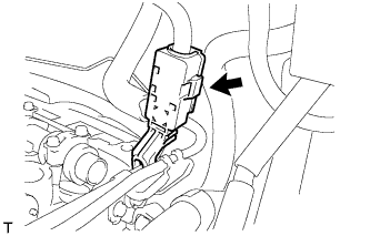 |
Remove the fuel pipe clamp.
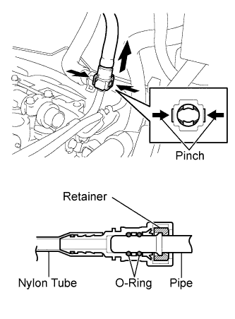 |
Pinch the retainer of the fuel tube connector, then pull out the fuel tube connector to disconnect the fuel tube from the fuel delivery pipe sub-assembly.
| 45. DISCONNECT BOOSTER VACUUM TUBE |
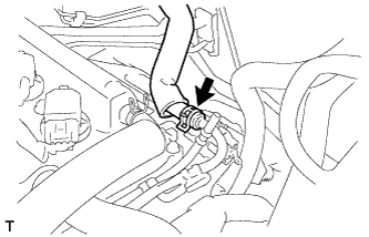 |
Disconnect the booster vacuum tube.
| 46. DISCONNECT CAMSHAFT POSITION SENSOR CONNECTOR |
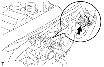 |
Disconnect the camshaft position sensor connector.
| 47. DISCONNECT ENGINE COOLANT TEMPERATURE SENSOR CONNECTOR |
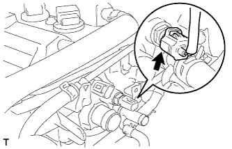 |
Disconnect the engine coolant temperature sensor connector.
| 48. DISCONNECT HEATED OXYGEN SENSOR CONNECTOR |
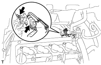 |
Remove the bolts and separate the sensor bracket.
Disconnect the heated oxygen sensor connector.
| 49. DISCONNECT HEATER WATER HOSE INLET A |
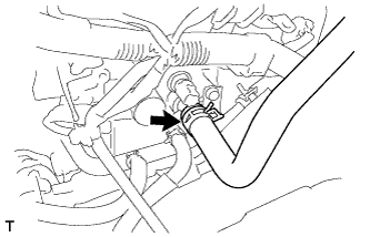 |
Disconnect heater water inlet hose A.
| 50. SEPARATE WATER BY-PASS PIPE NO. 1 |
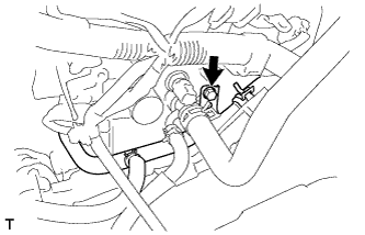 |
Remove the bolt and separate water by-pass pipe No. 1.
| 51. DISCONNECT WIRE HARNESS |
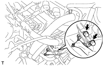 |
Remove the 2 bolts and disconnect the wire harness.
| 52. SEPARATE EXHAUST PIPE ASSEMBLY FRONT |
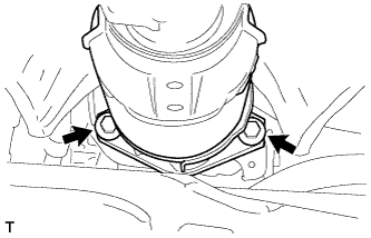 |
Remove the 2 bolts and 2 compression springs and separate the exhaust pipe assembly front.
| 53. REMOVE MANIFOLD SUPPORT BRACKET |
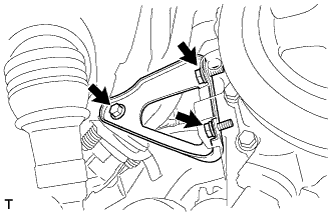 |
Remove the 3 bolts and remove the manifold support bracket.
| 54. REMOVE FAN & GENERATOR V BELT |
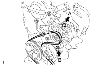 |
Loosen bolts A and B.
Release the fan and generator V belt tension and remove the fan and generator V belt.
| 55. REMOVE GENERATOR ASSEMBLY |
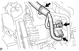 |
Remove the terminal cap.
Separate the connector and harness clamp.
Remove the nut and remove terminal B.
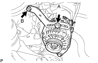 |
Remove fan belt adjusting slider fixing bolts A and B and remove the fan belt adjusting slider.
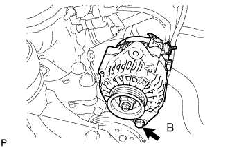 |
Remove fixing bolt B and remove the generator.
| 56. REMOVE IGNITION COIL NO. 1 |
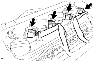 |
Disconnect the 4 ignition coil connectors.
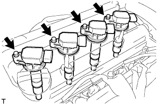 |
Remove the 4 bolts and 4 ignition coils.
| 57. REMOVE VENTILATION HOSE |
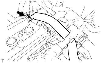 |
Disconnect the ventilation hose.
| 58. REMOVE VENTILATION HOSE NO. 2 |
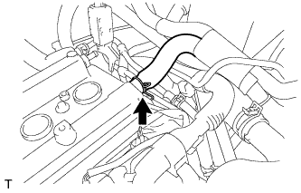 |
Disconnect ventilation hose No. 2.
| 59. REMOVE CYLINDER HEAD COVER SUB-ASSEMBLY (for RHD) |
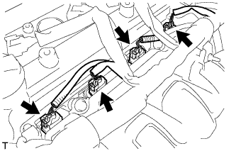 |
Disconnect the fuel injector connectors.
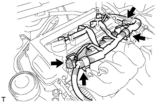 |
Disconnect the connector and 3 wire harness clamps shown in the illustration and disconnect the engine wire harness.
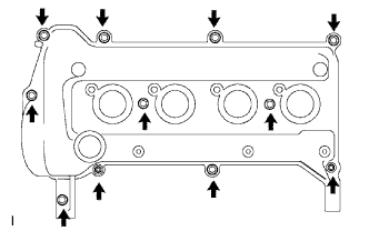 |
Remove the 9 bolts, 2 nuts and 2 seal washers and then remove the cylinder head cover sub-assembly.
| 60. REMOVE CYLINDER HEAD COVER SUB-ASSEMBLY (for LHD) |
|
Disconnect the fuel injector connectors.
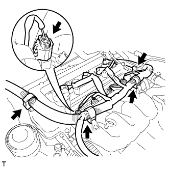 |
Disconnect the connector and 3 wire harness clamps shown in the illustration and disconnect the engine wire harness.
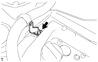 |
Remove the bolt and remove the wire harness bracket.
|
Remove the 9 bolts, 2 nuts and 2 seal washers and remove the cylinder head cover sub-assembly.
| 61. REMOVE ENGINE MOUNTING INSULATOR SUB-ASSEMBLY RH |
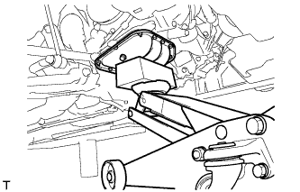 |
Place a wooden block on a jack underneath the engine.
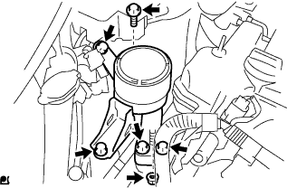 |
Remove the 5 bolts and nut and remove the engine mounting insulator sub-assembly RH.
| 62. REMOVE CRANKSHAFT DAMPER SUB-ASSEMBLY |
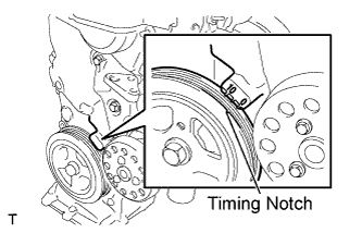 |
Set cylinder No. 1 to TDC/compression.
Turn the crankshaft damper sub-assembly, and align its timing notch with timing mark "0" of the oil pump.
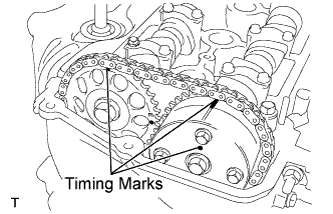 |
Check that the timing marks on the camshaft timing sprocket and the camshaft timing gear are all facing upward as shown in the illustration.
If not, turn the crankshaft 1 complete revolution (360°) and align the marks as above.
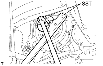 |
Using 2 SSTs, loosen the bolt while holding the crankshaft damper sub-assembly.
Remove the SSTs and the bolt.
Remove the crankshaft damper sub-assembly.
| 63. REMOVE CRANKSHAFT POSITION SENSOR |
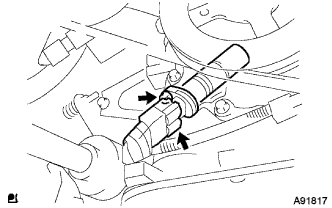 |
Disconnect the crankshaft position sensor connector.
Remove the bolt and remove the crankshaft position sensor.
| 64. REMOVE CAMSHAFT TIMING OIL CONTROL VALVE ASSEMBLY |
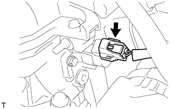 |
Disconnect the camshaft timing oil control valve assembly connector.
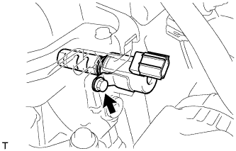 |
Remove the bolt and nut and remove the camshaft timing oil control valve assembly.
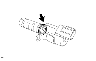 |
Remove the O-ring from the camshaft timing oil control valve assembly.
| 65. REMOVE WATER PUMP PULLEY |
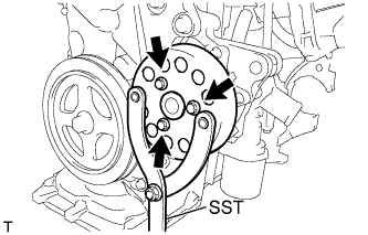 |
Using SST, hold the water pump pulley.
Remove the 3 bolts and remove the water pump pulley.
| 66. REMOVE WATER PUMP ASSEMBLY |
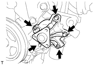 |
Remove the 3 bolts and 2 nuts and remove the water pump assembly and gasket.
| 67. REMOVE TRANSVERSE ENGINE ENGINE MOUNTING BRACKET |
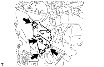 |
Remove the 4 bolts and remove the transverse engine engine mounting bracket.
| 68. REMOVE OIL PUMP ASSEMBLY |
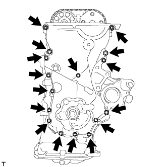 |
Remove the 15 bolts and the nut.
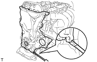 |
Using a screwdriver with its tip wrapped in protective tape, prize the oil pump assembly to remove it.
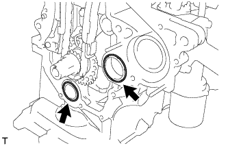 |
Remove the 2 O-rings from the cylinder block and oil pan sub-assembly.
| 69. REMOVE OIL PUMP SEAL |
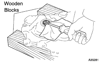 |
Using a screwdriver with its tip wrapped in protective tape, remove the oil pump seal.
| 70. REMOVE CHAIN TENSIONER ASSEMBLY NO. 1 |
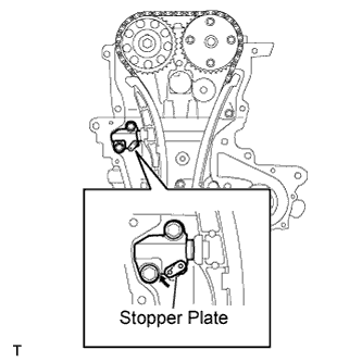 |
Pull up the stopper plate and hold it with its lock released.
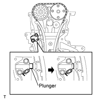 |
Unlock the plunger of the tensioner and push it in to the end.
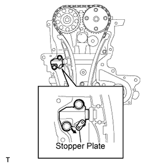 |
Pull down the stopper plate with the plunger pushed to the end and lock the plunger.
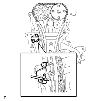 |
Insert a 3 mm (0.12 in.) diameter bar into the hole in the stopper plate and lock the plunger.
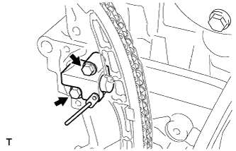 |
Remove the 2 bolts and remove chain tensioner assembly No. 1.
| 71. REMOVE CHAIN TENSIONER SLIPPER |
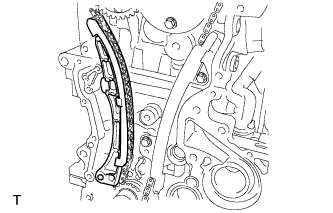 |
Remove the chain tensioner slipper.
| 72. REMOVE CHAIN VIBRATION DAMPER NO. 1 |
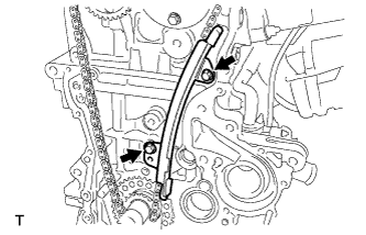 |
Remove the 2 bolts and remove chain vibration damper No. 1.
| 73. REMOVE CHAIN SUB-ASSEMBLY |
| 74. REMOVE CAMSHAFT |
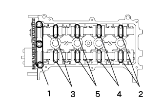 |
Using several steps, loosen and remove the 19 bearing cap bolts uniformly in the sequence shown in the illustration, and then remove camshaft bearing cap No. 1 and camshaft bearing cap No. 2.
Remove the camshaft and camshaft No. 2.
| 75. REMOVE CYLINDER HEAD SUB-ASSEMBLY |
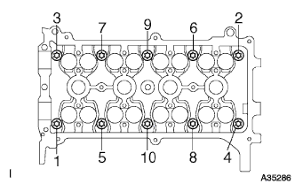 |
Using several steps, loosen and remove the 10 cylinder head bolts uniformly with an 8 mm bi-hexagon wrench in the sequence shown in the illustration. Remove the 10 cylinder head bolts and the plate washers.
| 76. REMOVE CYLINDER HEAD GASKET |
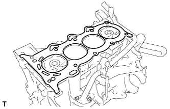 |
Remove the cylinder head gasket.
| 77. REMOVE EXHAUST MANIFOLD HEAT INSULATOR NO. 1 |
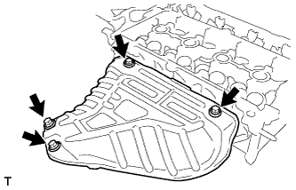 |
Remove the 4 bolts and remove exhaust manifold heat insulator No. 1.
| 78. REMOVE EXHAUST MANIFOLD |
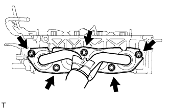 |
Remove the 3 bolts and 2 nuts and remove the exhaust manifold.
| 79. REMOVE HARNESS BRACKET |
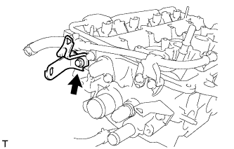 |
Remove the bolt and remove the harness bracket.
| 80. REMOVE BOOSTER VACUUM TUBE |
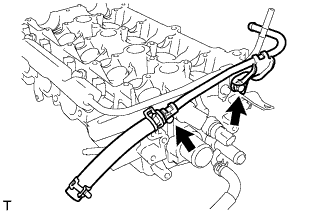 |
Remove the 2 bolts and remove the booster vacuum tube.
| 81. REMOVE CAMSHAFT POSITION SENSOR |
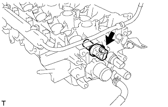 |
Remove the bolt and remove the camshaft position sensor.
| 82. REMOVE ENGINE COOLANT TEMPERATURE SENSOR |
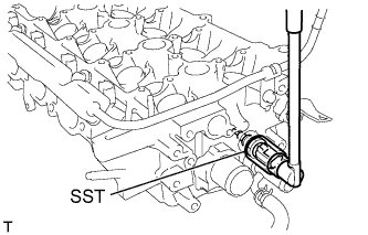 |
Using SST, remove the engine coolant temperature sensor connector.
| 83. REMOVE WATER BY-PASS HOSE |
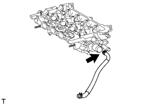 |
Remove the water by-pass hose.
| 84. REMOVE HARNESS BRACKET |
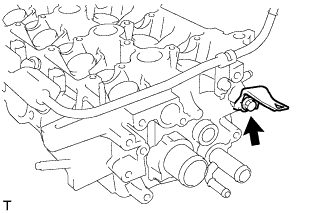 |
Remove the bolt and remove the harness bracket.
| 85. REMOVE FUEL DELIVERY PIPE SUB-ASSEMBLY |
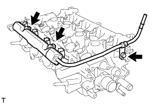 |
Remove the 3 bolts and remove the fuel delivery pipe sub-assembly together with the 4 fuel injectors.
| 86. REMOVE FUEL INJECTOR ASSEMMBLY |
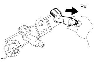 |
Pull the 4 fuel injector assemblies out of the fuel delivery pipe sub-assembly.
| 87. REMOVE DELIVERY PIPE NO. 1 SPACER |
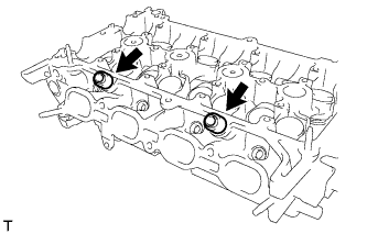 |
Remove the 2 delivery pipe No. 1 spacers.
| 88. REMOVE INJECTOR VIBRATION INSULATOR |
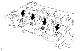 |
Remove the 4 injector vibration insulators.