OIL PUMP > INSTALLATION |
| 1. INSTALL OIL PUMP ASSEMBLY |
|
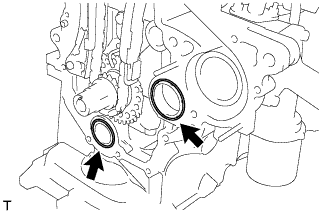
Install 2 new O-rings onto the 2 locations shown in the illustration.
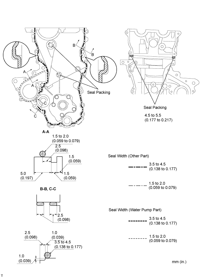
Apply seal packing to the oil pump assembly, cylinder head and cylinder block as shown in the illustration.
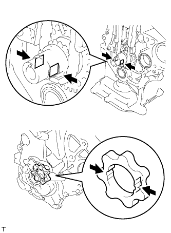 |
Align the keyway of the oil pump rotor with the rectangular portion of the crankshaft, and slide the oil pump into place.
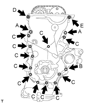 |
Install the oil pump assembly with the 15 bolts and the nut. Tighten the bolts and nut uniformly in several steps.
| 2. INSTALL TRANSVERSE ENGINE ENGINE MOUNTING BRACKET |
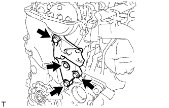 |
Install the transverse engine engine mounting bracket with the 4 bolts.
| 3. INSTALL WATER PUMP ASSEMBLY |
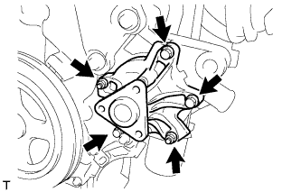 |
Install the water pump assembly through a new gasket with the 3 bolts and 2 nuts.
| 4. INSTALL WATER PUMP PULLEY |
Provisionally install the water pump pulley with the 3 bolts.
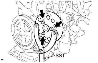 |
Using SST, hold the water pump pulley.
Tighten the 3 bolts to the specified torque.
| 5. INSTALL CAMSHAFT TIMING OIL CONTROL VALVE ASSEMBLY |
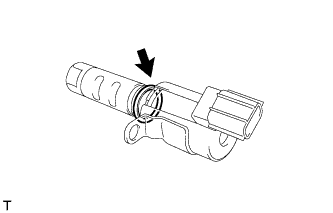 |
Apply a light coat of engine oil to a new O-ring and install it onto the camshaft timing oil control valve assembly.
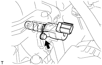 |
Install the camshaft timing oil control valve assembly with the bolt.
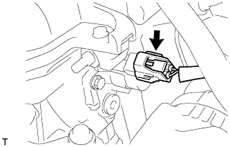 |
Connect the camshaft timing oil control valve assembly connector.
| 6. INSTALL CRANKSHAFT POSITION SENSOR |
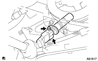 |
Apply a light coat of engine oil to the O-ring on the crankshaft position sensor.
Install the crankshaft position sensor with the bolt.
Connect the crankshaft position sensor connector.
| 7. INSTALL CRANKSHAFT DAMPER SUB-ASSEMBLY |
Align the pin hole of the crankshaft damper with the pin and install the crankshaft damper sub-assembly.
Provisionally install the bolt.
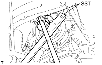 |
Using 2 SSTs, tighten the bolt while holding the crankshaft damper sub-assembly.
| 8. INSTALL ENGINE MOUNTING INSULATOR SUB-ASSEMBLY RH (for Hatchback) |
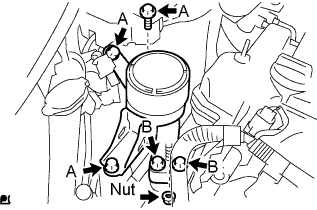 |
Install the engine mounting insulator sub-assembly RH with the 5 bolts and nut.
| 9. INSTALL ENGINE MOUNTING INSULATOR SUB-ASSEMBLY RH (for Sedan) |
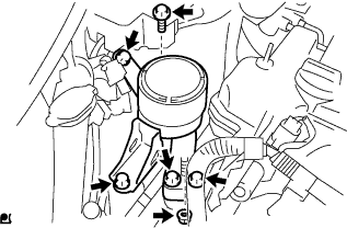 |
Install the engine mounting insulator sub-assembly RH with the 5 bolts and nut.
| 10. INSTALL CYLINDER HEAD COVER SUB-ASSEMBLY (for RHD) |
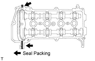 |
Apply seal packing to the cylinder head as shown in the illustration.
Install the cylinder head cover sub-assembly with the 9 bolts, 2 nuts and 2 seal washers.
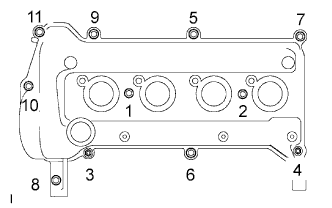 |
Tighten the 9 bolts and 2 nuts in the sequence shown in the illustration.
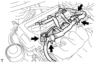 |
Connect the connector and wire harness clamp as shown in the illustration and connect the engine wire harness.
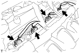 |
Connect the fuel injector connectors.
| 11. INSTALL CYLINDER HEAD COVER SUB-ASSEMBLY (for LHD) |
|
Disconnect the fuel injector connectors.
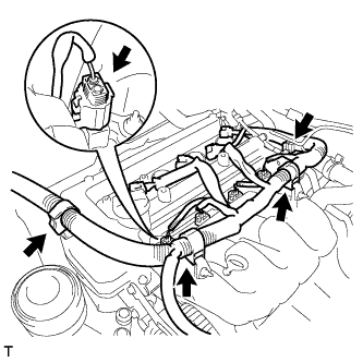 |
Disconnect the connector and 3 wire harness clamps shown in the illustration and disconnect the engine wire harness.
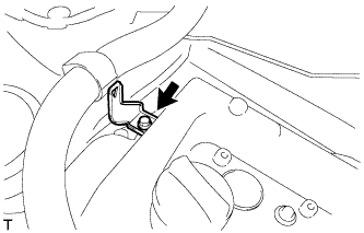 |
Remove the bolt and remove the wire harness bracket.
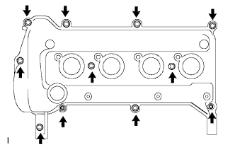 |
Remove the 9 bolts, 2 nuts and 2 seal washers and remove the cylinder head cover sub-assembly.
| 12. INSTALL VENTILATION HOSE NO. 2 |
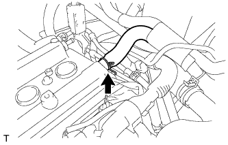 |
Connect ventilation hose No. 2.
| 13. INSTALL VENTILATION HOSE |
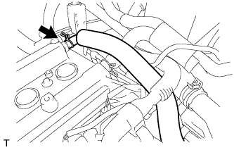 |
Connect the ventilation hose.
| 14. INSTALL IGNITION COIL NO. 1 |
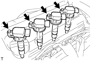 |
Install the 4 ignition coils with the 4 bolts.
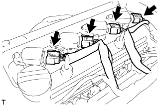 |
Connect the 4 ignition coil connectors.
| 15. INSTALL GENERATOR ASSEMBLY |
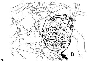 |
Provisionally install the generator with fixing bolt B.
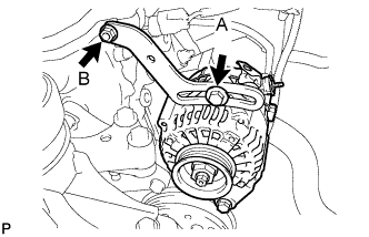 |
Provisionally install the fan belt adjusting slider with fan belt adjusting slider fixing bolts A and B, then move the generator toward the cylinder block and tighten bolt B.
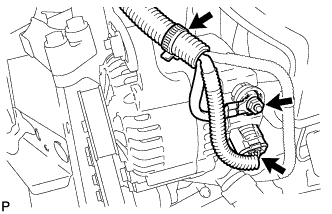 |
Install the connector and wire harness clamp.
Install terminal B with the nut.
Install the terminal cap.
| 16. INSTALL FAN & GENERATOR V BELT |
Provisionally install the fan and generator V belt onto each pulley.
| 17. ADJUST FAN & GENERATOR V BELT |
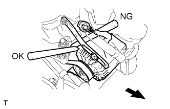 |
Insert an adjusting bar between the engine mounting bracket and generator assembly. Pull the adjusting bar towards the vehicle front to adjust the generator V belt tension.
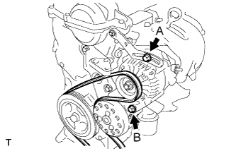 |
First tighten bolt A, then tighten bolt B.
| 18. INSPECT FAN & GENERATOR V BELT |
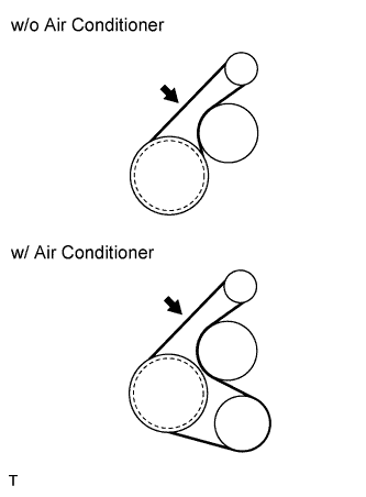 |
Check the V belt deflection and tension.
| Item | Specified Condition |
| New belt | 8.0 to 9.0 mm (0.31 to 0.35 in) |
| Used belt | 12.5 to 13.5 mm (0.49 to 0.53 in) |
| Item | Specified Condition |
| New belt | 700 to 800 N (71 to 82 kg, 157 to 180 lb) |
| Used belt | 300 to 400 N (31 to 41 kg, 67 to 90 lb) |
| 19. CONNECT CABLE TO NEGATIVE BATTERY TERMINAL |
| 20. ADD ENGINE OIL |
| 21. ADD ENGINE COOLANT |
Tighten all the plugs.
Pour engine coolant into the radiator assembly until it overflows.
Check the engine coolant level inside the radiator assembly by squeezing the inlet and outlet radiator hoses several times by hand. If the engine coolant level goes down, add engine coolant.
Install the radiator cap sub-assembly securely.
Slowly pour engine coolant into the radiator reservoir until it reaches the FULL line.
Warm up the engine until the cooling fan operates.
Set the air conditioning as follows while warming up the engine.
| Item | Manual air conditioning system | Automatic air conditioning system |
| Set control as follows | Fan speed - Any setting except "OFF" Temperature - Toward WARM Air conditioning switch "OFF" | Fan speed - Any setting except "OFF" Temperature - To the highest temperature Air conditioning switch "OFF" "AUTO" switch "OFF" |
Maintain the engine speed at 2,000 to 2,500 rpm and warm up the engine until the cooling fan operates.
Stop the engine and wait until the coolant cools down.
If the engine coolant level is below the full level, perform steps (b) through (g) again and repeat the operation until the engine coolant level stays at the full level.
Recheck the engine coolant level inside the radiator reservoir tank assembly. If it is below the full level, add the engine coolant.
Visually check for engine coolant leakage.
| 22. CHECK ENGINE OIL LEVEL |
Warm up the engine, then stop the engine and wait for 5 minutes. Check that the engine oil level is between the low and full marks on the oil level gauge.
If the engine oil level is low, check for oil leakage and add engine oil up to the full level mark.
| 23. CHECK FOR ENGINE OIL LEAKAGE |
| 24. CHECK FOR ENGINE COOLANT LEAKAGE |
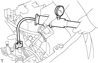 |
Fill the radiator assembly with engine coolant, then attach a radiator cap tester.
Pump the tester to 137 kPa (1.4 kgf/cm2, 19.9 psi), then check that the pressure does not drop.
If the pressure drops, check the hoses, radiator assembly and water pump assembly for leakage. If there are no signs or traces of external engine coolant leakage, check the heater core, cylinder block and head.
| 25. INSTALL CYLINDER HEAD COVER NO. 2 |
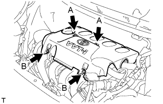 |
Tighten 2 A nuts, then 2 B nuts .
| 26. INSTALL ENGINE UNDER COVER RH |
| 27. INSTALL FRONT WHEEL RH |
| 28. INSTALL ENGINE UNDER COVER SUB-ASSEMBLY (for Rough Road Area Specification Vehicles) |