ENGINE UNIT > INSPECTION |
| 1. INSPECT CAMSHAFT TIMING GEAR ASSEMBLY (for Unleaded Gasoline Specification Vehicle) |
Check the lock of camshaft timing gear.
Clamp the camshaft in a vice, and check that the camshaft timing gear is locked.
![]() |
Release the lock pin.
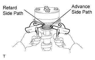
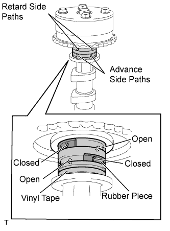
Cover the 4 oil paths of the cam journal with tape as shown in the illustration.
Puncture the tape covering the advance oil path and the retard oil path on the opposite side from the advance oil path.
![]() |
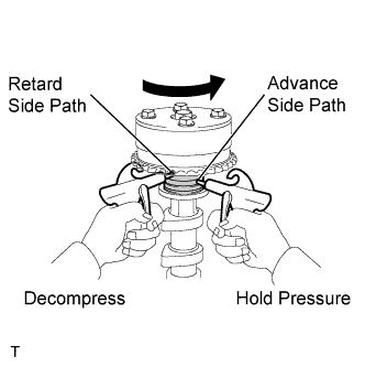
Apply air at about 150 kPa (1.5 kgf*cm2) pressure into the 2 broken paths (the advance side path and the retard side path).
![]() |
Confirm that the camshaft timing gear assembly revolves in the timing advance direction when the air pressure on the timing retard path is reduced.
When the camshaft timing gear reaches the most advanced position, release the air pressure on the timing retard side path, and then release the air pressure on the timing advance side path.
Check the revolution.
Rotate the valve timing assembly back and forth several times, except where the lock pin meets it at the most retarded angle. Check the movable range and that it rotates smoothly.
Check the lock in the most retarded position.
Confirm that the camshaft timing gear assembly is locked in the most retarded position.
| 2. INSPECT CHAIN SUB-ASSEMBLY |
![]() |
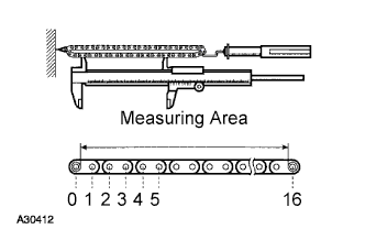
Using a spring scale, apply 140 N (14.3 kgf, 31.5 lb) to the timing chain and measure its length.
| 3. INSPECT CHAIN TENSIONER ASSEMBLY NO. 1 |
![]() |
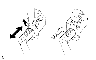
Check that the plunger moves smoothly when the ratchet pawl is raised with your finger.
Release the ratchet pawl and check that the plunger is locked in place by the ratchet pawl and does not move when pushed with your finger.
| 4. INSPECT CAMSHAFT TIMING GEAR ASSEMBLY (for Unleaded Gasoline Specification Vehicle) |
![]() |
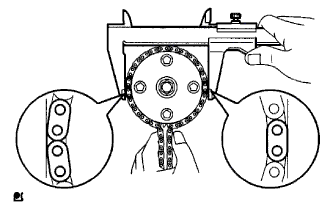
Wrap the chain around the timing sprocket.
Using vernier calipers, measure the diameter of the timing gear with the chain.
| 5. INSPECT CAMSHAFT TIMING SPROCKET (for Leaded Gasoline Specification Vehicle) |
![]() |
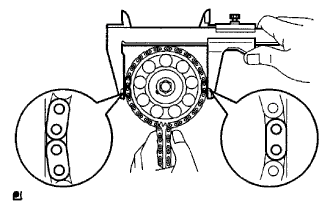
Wrap the chain around the timing sprocket.
Using vernier calipers, measure the diameter of the timing gear with the chain.
| 6. INSPECT CAMSHAFT TIMING SPROCKET |
![]() |
Wrap the chain around the timing sprocket.
Using vernier calipers, measure the diameter of the timing gear with the chain.
| 7. INSPECT CHAIN TENSIONER SLIPPER |
![]() |
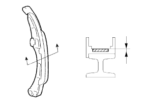
Check the chain tensioner slipper.
| 8. INSPECT CHAIN VIBRATION DAMPER NO. 1 |
![]() |
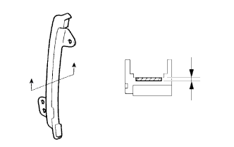
Check the vibration damper.
| 9. INSPECT CONNECTING ROD THRUST CLEARANCE |
![]() |
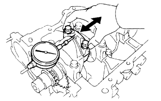
Using a dial indicator, measure the thrust clearance while moving the connecting rod back and forth.
| 10. INSPECT CONNECTING ROD OIL CLEARANCE |
Check that the matchmarks on the connecting rod and cap are aligned to ensure correct reassembly.
![]() |
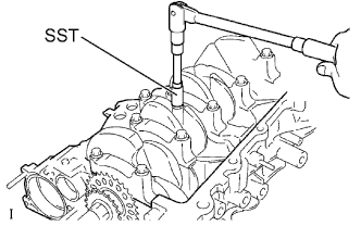
Using SST, remove the 2 connecting rod cap bolts.
Clean the crank pin and bearing.
Check the crank pin and bearing for pitting and scratches.
![]() |
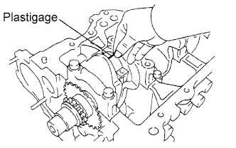
Lay a strip of Plastigage across the crank pin.
![]() |
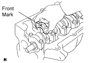
Make sure that the connecting rod and its cap are in the correct combination and that the front mark of the cap is facing in the correct mounting orientation, then install the cap onto the connecting rod.
Apply a light coat of engine oil to the threads of the connecting rod cap bolts.
![]() |
Using SST, tighten the bolts in several steps to the specified torque.
![]() |
Mark the front of the connecting cap bolts with paint.
Retighten the cap bolts by 90° as shown in the illustration.
Remove the 2 bolts, connecting rod cap and lower bearing.
![]() |
Measure the plastigage at its widest point.
![]() |
When replacing a bearing, replace it with one with the same number as marked on the connecting rod. There are 3 sizes of standard bearings, marked 1, 2 and 3 accordingly.
| Mark | mm (in.) |
| 1 | 1.491 to 1.494 (0.0587 to 0.0588) |
| 2 | 1.494 to 1.497 (0.0588 to 0.0589) |
| 3 | 1.497 to 1.500 (0.0589 to 0.0591) |
| 11. INSPECT CRANKSHAFT THRUST CLEARANCE |
![]() |
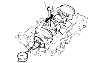
Using a dial indicator, measure the thrust clearance while moving the crankshaft back and forth with a screwdriver.
| 12. INSPECT CYLINDER BLOCK FOR WARPAGE |
![]() |
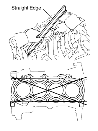
Using a precision straightedge and feeler gauge, measure the warpage of the surface which is in contact with the cylinder head gasket.
| 13. INSPECT CYLINDER BORE |
![]() |
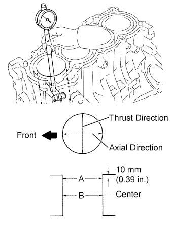
Using a cylinder gauge, measure the cylinder bore diameter at positions A and B in the thrust and axial directions.
Calculate the difference between the maximum diameter and the minimum diameter of the 4 measured values.
| 14. INSPECT WITH PIN PISTON SUB-ASSEMBLY (for Unleaded Gasoline Specification Vehicle) |
![]() |
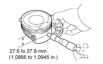
Using a micrometer, measure the piston diameter at a right angle to the piston pin center line, and at the position 27.6 to 27.8 mm (1.0866 to 1.0945 in.) from top of the piston head.
Using a caliper gauge, measure the piston pin hole diameter.
![]() |
Using a micrometer, measure the piston pin diameter.
Subtract the piston pin diameter measurement from the piston pin hole diameter measurement to calculate the oil clearance.
| 15. INSPECT WITH PIN PISTON SUB-ASSEMBLY (for Leaded Gasoline Specification Vehicle) |
![]() |
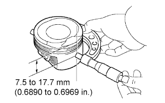
Using a micrometer, measure the piston diameter at right angle to the piston pin center line, and at the position of 17.5 to 17.7 mm (0.6890 to 0.6969 in.) from top of the piston head.
Using a caliper gauge, measure the piston pin hole diameter of the piston.
![]() |
Using a micrometer, measure the piston pin diameter.
Subtract the piston pin diameter measurement from the piston pin hole diameter measurement to calculate the oil clearance.
| 16. INSPECT PISTON CLEARANCE |
Subtract the piston diameter measurement from the cylinder bore diameter measurement to calculate the oil clearance.
| 17. INSPECT CONNECTING ROD SUB-ASSEMBLY |
![]() |
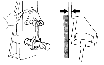
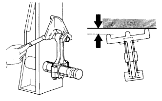
Using a rod aligner and feeler gauge, check the connecting rod alignment.
Check for misalignment.
![]() |
Check for twist.
| 18. INSPECT RING GROOVE CLEARANCE |
![]() |
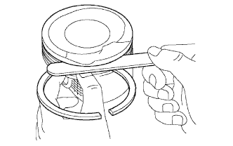
Using a feeler gauge, measure the clearance between a new piston ring and the wall of the ring groove.
| 19. INSPECT PISTON RING END GAP |
![]() |
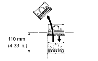
Using a piston, push the piston ring, a little beyond the bottom of the ring travel, 110 mm (4.33 in.) from the top of the cylinder block.
![]() |
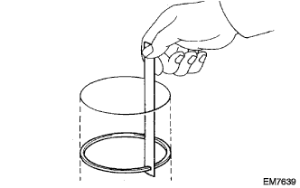
Using a feeler gauge, measure the end gap.
| 20. INSPECT CONNECTING ROD BOLT |
![]() |
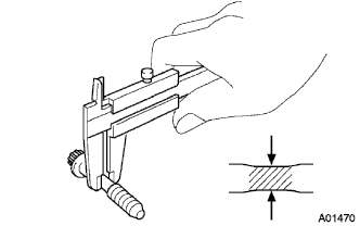
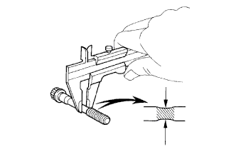
Using vernier calipers, measure the diameter of the bolt at the elongated portion.
| 21. INSPECT CRANKSHAFT |
![]() |
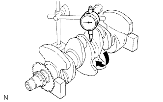
Using a dial indicator and V-blocks, measure the circle runout as shown in the illustration.
![]() |
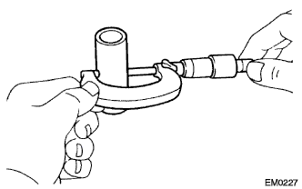
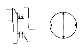
Using a micrometer, measure the diameter of each main journal.
Check each main journal for taper and out-of-roundness as shown.
![]() |
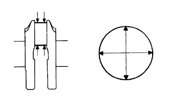
Using a micrometer, measure the diameter of each crank pin.
Check each crank pin for taper and out-of-roundness as shown.
![]() |
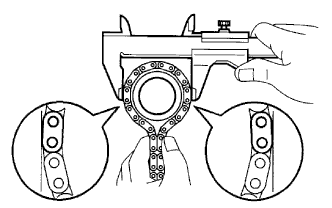
Wrap the chain around the timing sprocket.
Using vernier calipers, measure the timing sprocket diameter with the chain.
| 22. INSPECT CRANKSHAFT BEARING CAP SET BOLT |
![]() |
Using vernier calipers, measure the tension portion diameter at the elongated portion.
| 23. INSPECT CRANKSHAFT OIL CLEARANCE |
Clean each main journal and bearing.
Install the bearing onto the cylinder block and bearing cap.
Place the crankshaft onto the cylinder block.
![]() |
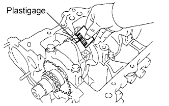
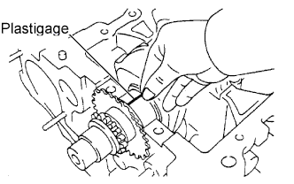
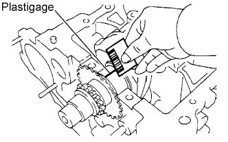
Lay a strip of Plastigage across each journal.
![]() |
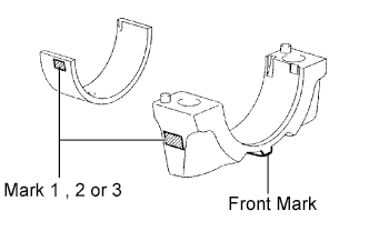
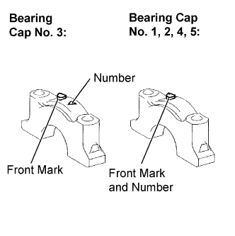
Examine the front marks and numbers and install the bearing cap onto the cylinder block.
Apply a light coat of engine oil to the threads of the bearing cap bolts.
![]() |
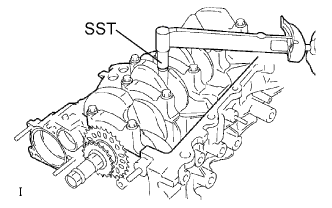
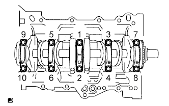
Tighten the bolts in several steps to the specified torque in the sequence shown in the illustration. (*1)
![]() |
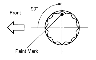
Mark the front of the bearing cap bolts with paint.
Retighten the bearing cap bolts by 90° in the same sequence as step (*1).
Check that the painted mark is now at a 90° angle from the front.
Remove the bearing cap sub-assembly.
![]() |
Measure the Plastigage at its widest point.
![]() |
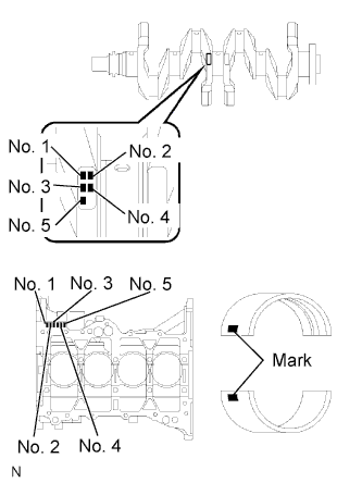
When replacing a standard bearing, replace it with one with the same number. If the number of the bearing cannot be found on the bearing shell, select the correct bearing by adding together the numbers imprinted on the cylinder block and crankshaft, then select the bearing with the same number as the total. There are 4 sizes of standard bearings, marked 1, 2, 3 and 4 accordingly.
| Cylinder Block (A) + Crankshaft (B) | 0 to 2 | 3 to 5 | 6 to 8 | 9 to 11 |
| Use Bearing | 1 | 2 | 3 | 4 |
| Item | Mark | mm (in.) |
| Cylinder block main journal bore diameter (A) | 0 1 2 3 4 5 6 | 50.000 to 50.003 (1.96850 to 1.96862) 50.003 to 50.005 (1.96862 to 1.96870) 50.005 to 50.007 (1.96870 to 1.96878) 50.007 to 50.010 (1.96878 to 1.96890) 50.010 to 50.012 (1.96890 to 1.96898) 50.012 to 50.014 (1.96898 to 1.96906) 50.014 to 50.016 (1.96906 to 1.96913) |
| Crankshaft main journal diameter (B) | 0 1 2 3 4 5 | 45.998 to 46.000 (1.81094 to 1.81102) 45.996 to 45.998 (1.81087 to 1.81094) 45.994 to 45.996 (1.81079 to 1.81087) 45.992 to 45.994 (1.81071 to 1.81079) 45.990 to 45.992 (1.81063 to 1.81071) 45.988 to 45.990 (1.81055 to 1.81063) |
| Standard bearing center wall thickness | 1 2 3 4 | 1.992 to 1.995 (0.07843 to 0.07854) 1.995 to 1.998 (0.07854 to 0.07866) 1.998 to 2.001 (0.07866 to 0.07878) 2.001 to 2.004 (0.07878 to 0.07890) |