ENGINE UNIT > DISASSEMBLY |
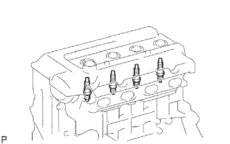
| 1. REMOVE SPARK PLUG |
|
Using a spark plug wrench, remove the 4 spark plugs.
| 2. REMOVE KNOCK SENSOR |
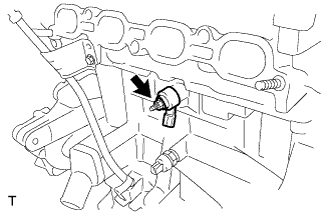 |
Remove the nut and remove the knock sensor.
| 3. REMOVE ENGINE OIL PRESSURE SWITCH ASSEMBLY |
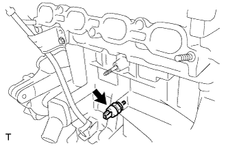 |
Using a 24 mm deep socket wrench, remove the oil pressure switch.
| 4. REMOVE ENGINE COOLANT TEMPERATURE SENSOR |
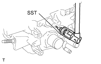 |
Using SST, remove the engine coolant temperature sensor.
| 5. REMOVE WATER INLET |
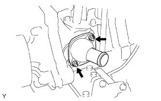 |
Remove the 2 nuts and remove the water inlet.
| 6. REMOVE THERMOSTAT |
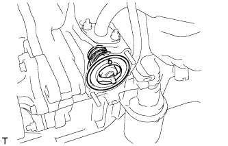 |
Remove the thermostat.
Remove the gasket from the thermostat.
| 7. REMOVE OIL FILLER CAP SUB-ASSEMBLY |
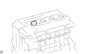 |
Remove the oil filler cap from the cylinder head cover.
| 8. REMOVE OIL FILLER CAP GASKET |
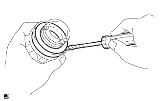 |
Using a screwdriver, remove the gasket from the oil filler cap.
| 9. REMOVE CRANKSHAFT POSITION SENSOR |
Remove the bolt and the crankshaft position sensor.
| 10. REMOVE VENTILATION VALVE SUB-ASSEMBLY |
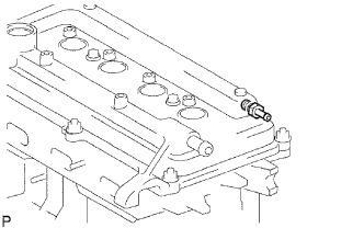 |
Remove the ventilation valve from the cylinder head cover.
| 11. REMOVE CYLINDER HEAD COVER SUB-ASSEMBLY |
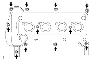 |
Remove the 9 bolts, 2 nuts and 2 seal washers and then remove the cylinder head cover sub-assembly.
| 12. REMOVE CYLINDER HEAD COVER GASKET |
Remove the gasket from the cylinder head cover.
| 13. REMOVE CAMSHAFT TIMING OIL CONTROL VALVE ASSEMBLY (for Unleaded Gasoline Specification Vehicle) |
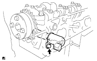 |
Remove the bolt and the camshaft timing oil control valve.
| 14. REMOVE OIL LEVEL GAUGE GUIDE |
Remove the bolt and the oil level gauge guide.
| 15. REMOVE WATER PUMP PULLEY |
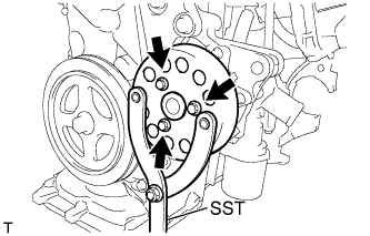 |
Using SST, hold the pump pulley.
Remove the 3 bolts and the pump pulley.
| 16. REMOVE CRANKSHAFT DAMPER SUB-ASSEMBLY |
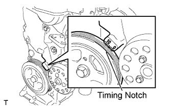 |
Set cylinder No. 1 to TDC/compression.
Turn the crankshaft damper sub-assembly, and align its timing notch with timing mark "0" of the oil pump.
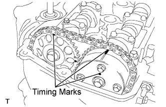 |
for Unleaded Gasoline Specification Vehicle:
Check that the timing marks on the camshaft timing sprocket and the camshaft timing gear are all facing upward, as shown in the illustration.
If not, turn the crankshaft 1 complete revolution (360°) and align the marks as above.
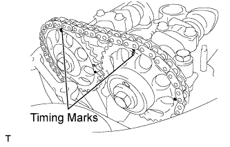 |
for Leaded Gasoline Specification Vehicle:
Check that both timing marks on the camshaft timing sprockets are facing upward as shown in the illustration.
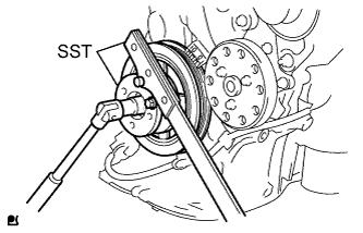 |
Using 2 SSTs, loosen the bolt while holding the crankshaft damper sub-assembly.
Remove the SSTs and the bolt.
Remove the crankshaft damper sub-assembly.
| 17. REMOVE TRANSVERSE ENGINE ENGINE MOUNTING BRACKET |
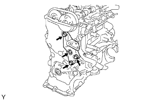 |
Remove the 4 bolts and remove the transverse engine mounting bracket.
| 18. REMOVE WATER PUMP ASSEMBLY |
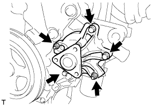 |
Remove the 3 bolts and 2 nuts and remove the water pump and gasket.
| 19. REMOVE OIL PUMP ASSEMBLY |
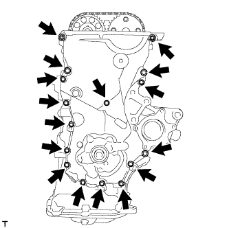 |
Remove the 15 bolts and nut.
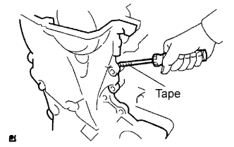 |
Using a screwdriver with its tip wrapped in protective tape, prize the oil pump assembly to remove it.
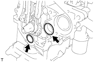 |
Remove the 2 O-rings from the cylinder block and oil pan sub-assembly.
| 20. REMOVE OIL PUMP SEAL |
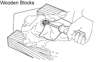 |
Using a screwdriver with its tip wrapped in tape, remove the oil seal.
| 21. REMOVE CHAIN TENSIONER ASSEMBLY NO.1 |
 |
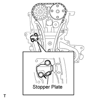 |
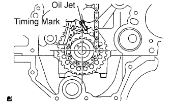
Pull up the stopper plate and hold it with its lock released.
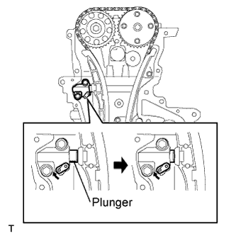 |
Unlock the plunger of the tensioner and push it in to the end.
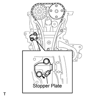 |
Pull down the stopper plate with the plunger pushed to the end and lock the plunger.
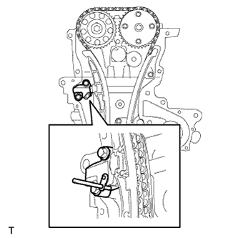 |
Insert a 3 mm (0.12 in.) diameter bar into the hole in the stopper plate and lock the plunger.
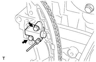 |
Remove the 2 bolts and remove the chain tensioner assembly No. 1.
| 22. REMOVE CHAIN TENSIONER SLIPPER |
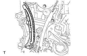 |
Remove the chain tensioner slipper.
| 23. REMOVE CHAIN VIBRATION DAMPER NO. 1 |
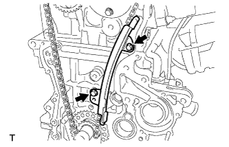 |
Remove the 2 bolts and remove chain vibration damper No. 1.
| 24. REMOVE CHAIN SUB-ASSEMBLY |
| 25. REMOVE FUEL DELIVERY PIPE SUB-ASSEMBLY |
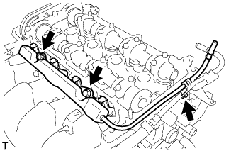 |
Remove the 3 bolts and remove the fuel delivery pipe sub-assembly with 4 fuel injectors.
| 26. REMOVE DELIVERY PIPE NO. 1 SPACER |
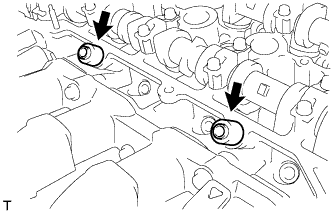 |
Remove the 2 delivery pipe No. 1 spacers.
| 27. REMOVE INJECTOR VIBRATION INSULATOR |
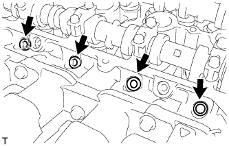 |
Remove the 4 injector vibration insulators.
| 28. REMOVE FUEL INJECTOR ASSEMBLY |
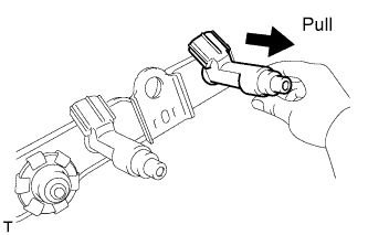 |
Pull the 4 fuel injector assemblies out of the fuel delivery pipe sub-assembly.
| 29. REMOVE CAMSHAFT POSITION SENSOR |
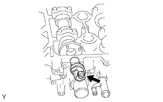 |
Remove the bolt and the camshaft position sensor.
| 30. REMOVE NO. 2 CAMSHAFT |
|
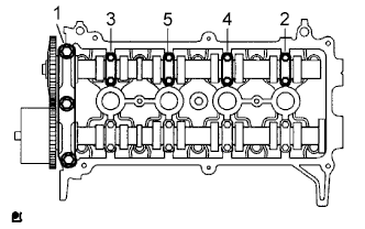 |
Using several steps, loosen and remove the 11 bearing cap bolts uniformly in the sequence shown in the illustration, then remove camshaft bearing cap No. 1, camshaft bearing cap No. 2 and camshaft No. 2.
| 31. REMOVE CAMSHAFT TIMING SPROCKET |
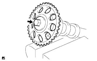 |
Clamp the camshaft in a vice.
Remove the flange bolt and the camshaft timing sprocket.
| 32. REMOVE CAMSHAFT |
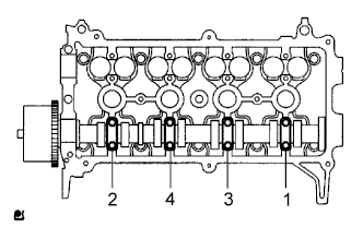 |
Using several steps, loosen and remove the 8 bearing cap bolts uniformly in the sequence shown in the illustration, then remove camshaft bearing cap No. 2 and the camshaft.
| 33. REMOVE CAMSHAFT TIMING GEAR ASSEMBLY (for Unleaded Gasoline Specification Vehicle) |
Clamp the camshaft in a vise, and confirm that it is locked.
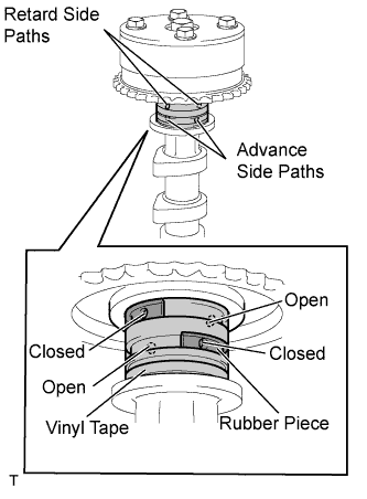 |
Cover the 4 oil paths of the cam journal with tape as shown in the illustration.
Puncture the tape covering the advance oil path and the retard oil path on the opposite side from the advance oil path.
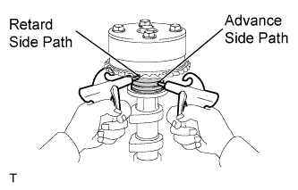 |
Apply at about 150 kPa (1.5 kgf*cm2) air pressure into the 2 broken paths (the advance side path and the retard side path).
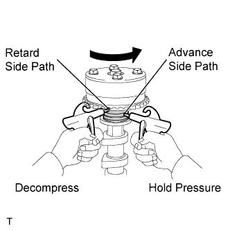 |
Confirm that the camshaft timing gear assembly revolves in the timing advance direction when the air pressure on the timing retard path is reduced.
When the camshaft timing gear reaches the most advanced position, release the air pressure on the timing retard side path, and then release the air pressure on the timing advance side path.
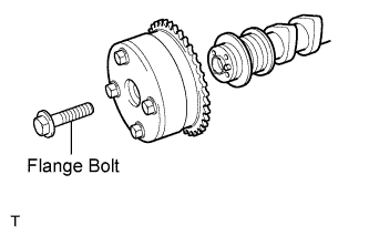 |
Remove the flange bolt and remove the camshaft timing gear assembly.
| 34. REMOVE CAMSHAFT TIMING SPROCKET (for Leaded Gasoline Specification Vehicle) |
Clamp the camshaft in a vice.
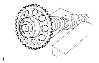 |
Remove the bolt and the camshaft timing sprocket.
| 35. REMOVE CYLINDER HEAD SUB-ASSEMBLY |
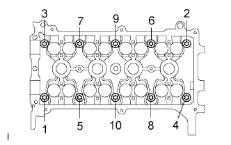 |
Using several steps, loosen and remove the 10 cylinder head bolts uniformly with an 8 mm bi-hexagon wrench in the sequence shown in the illustration. Remove the 10 cylinder head bolts and the plate washers.
| 36. REMOVE CYLINDER HEAD GASKET |
| 37. REMOVE OIL FILTER SUB-ASSEMBLY |
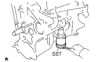 |
Using SST, remove the oil filter.
| 38. REMOVE OIL FILTER UNION |
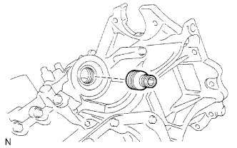 |
Using a 12 mm hexagon wrench, remove the oil filter union.
| 39. REMOVE ENGINE REAR OIL SEAL |
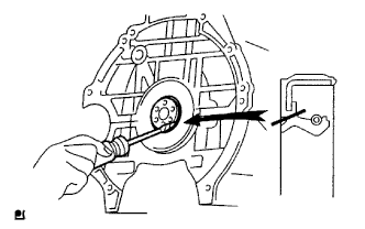 |
Using a knife, cut off the oil seal lip.
Using a screwdriver with its tip wrapped in protective tape, pry out the oil seal.
| 40. REMOVE OIL PAN SUB-ASSEMBLY NO. 2 |
Remove the oil pan drain plug and gasket.
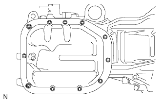 |
Remove the 9 bolts and 2 nuts.
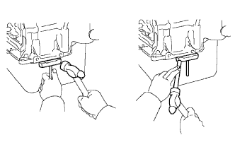 |
Insert the blade of an oil pan seal cutter between the No. 1 oil pan and No. 2 oil pan, and cut off the applied sealer and remove No. 2 oil pan.
| 41. REMOVE OIL STRAINER SUB-ASSEMBLY |
Remove the bolt and 2 nuts.
Remove the oil strainer and the gasket.
| 42. REMOVE OIL PAN SUB-ASSEMBLY |
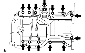 |
Loosen and remove the 13 bolts uniformly in several steps.
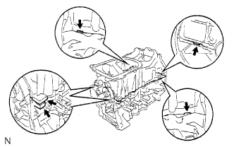 |
Using a screwdriver, remove oil pan No. 1 by prying between the cylinder block and oil pan No. 1.
Remove the 2 O-rings from the cylinder block.
| 43. REMOVE STUD BOLT |
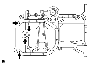 |
Remove the 4 stud bolts.
| 44. REMOVE PISTON SUB-ASSEMBLY WITH CONNECTING ROD |
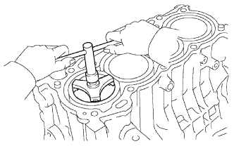 |
Using a ridge reamer, remove all the carbon from the top of the cylinder.
Push the piston, connecting the rod assembly and upper bearing through the top of the cylinder block to remove them.
| 45. REMOVE CONNECTING ROD BEARING |
| 46. REMOVE CRANKSHAFT |
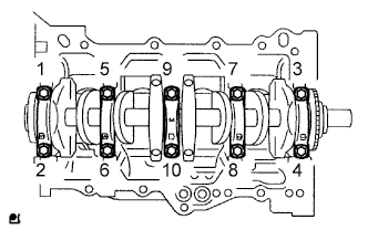 |
Using several steps, loosen and remove the 10 bearing cap sub-assembly bolts uniformly using 12 mm socket wrench in the sequence shown in the illustration.
Remove the bearing cap and the crankshaft.
| 47. REMOVE CRANKSHAFT BEARING |
| 48. REMOVE CRANKSHAFT THRUST WASHER UPPER |
| 49. REMOVE PISTON RING SET |
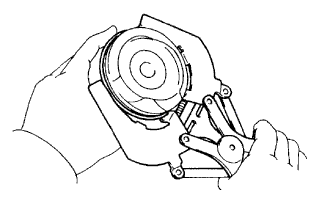 |
Using a piston ring expander, remove the 2 compression rings.
Remove the 2 side rails and the oil ring by hand.
| 50. REMOVE WITH PIN PISTON SUB-ASSEMBLY |
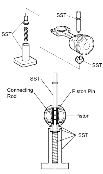 |
Using SST, press out the piston pin out of the piston.
| 51. REMOVE CYLINDER BLOCK WATER DRAIN COCK SUB-ASSEMBLY |
| 52. REMOVE STUD BOLT |
Using "Torx" socket wrench E5, remove the 7 stud bolts.
| 53. REMOVE RING PIN |
| 54. REMOVE STRAIGHT PIN |