ENGINE UNIT > REASSEMBLY |
| 1. INSTALL CYLINDER BLOCK WATER DRAIN COCK SUB-ASSEMBLY |
Apply adhesive to the end 2 or 3 threads of the drain union and install the water drain cock within 3 minutes of applying adhesive.
![]() |
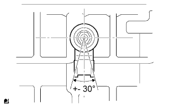
After applying the specified torque, rotate the drain union clockwise until its drain port faces downward.
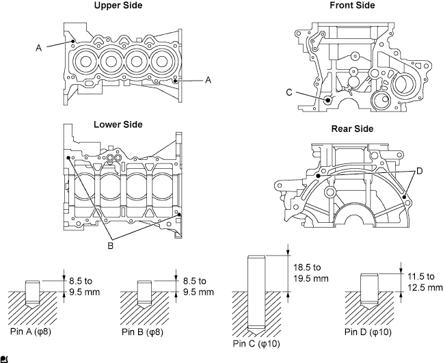
| 2. INSTALL STRAIGHT PIN |

Using a plastic-faced hammer, tap in the straight pin.
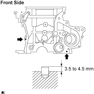
| 3. INSTALL OIL PUMP SET RING PIN |
![]() |
Using a plastic-faced hammer, tap in the ring pin.
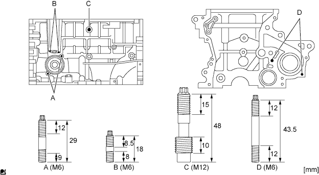
| 4. INSTALL STUD BOLT |

Using "Torx" socket wrench E5, install the 7 stud bolts.
| 5. INSTALL CRANKSHAFT BEARING |
![]() |
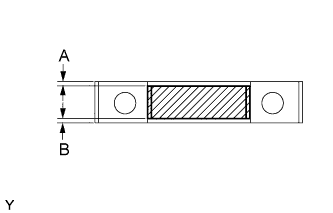
Align the crankshaft bearing (upper) with the oil hole of the cylinder block and install the bearing.
![]() |
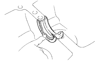
Align the crankshaft bearing (lower) with the bearing cap and install the crankshaft bearing cap.
| 6. INSTALL CRANKSHAFT THRUST WASHER UPPER |
![]() |
Install the 2 thrust washers onto the No. 3 journal position of the cylinder block with the oil grooves facing outward.
Apply engine oil to the upper bearing and install the crankshaft onto the cylinder block.
| 7. INSTALL CRANKSHAFT |
![]() |
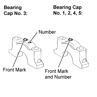
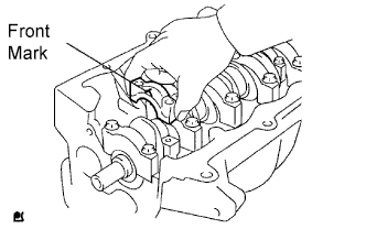
Examine the front marks and numbers and install the bearing caps onto the cylinder block.
Apply a light coat of engine oil to the threads of the bearing cap bolts.
![]() |
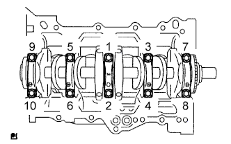
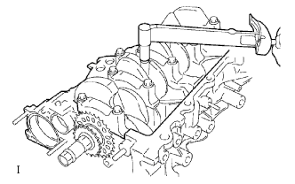
Tighten the bolts in several steps to the specified torque in the sequence shown in the illustration (*1).
![]() |
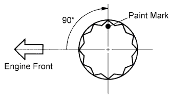
Mark the front of the bearing cap bolts with paint.
Retighten the bearing cap bolts by 90° in the same sequence as step (*1).
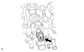
Check that the painted mark is now at a 90° angle from the front.
| 8. INSPECT CRANKSHAFT THRUST CLEARANCE |
![]() |
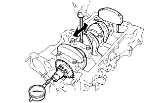
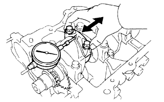
Using a dial indicator, measure the thrust clearance while moving the crankshaft back and forth with a screwdriver.
| 9. INSPECT CRANKSHAFT OIL CLEARANCE |
Clean each main journal and bearing.
Install the bearing onto the cylinder block and bearing cap.
Place the crankshaft onto the cylinder block.
![]() |
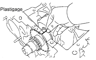
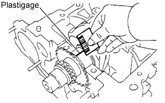
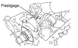
Lay a strip of Plastigage across each journal.
![]() |
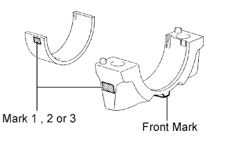
Examine the front marks and numbers and install the bearing cap onto the cylinder block.
Apply a light coat of engine oil to the threads of the bearing cap bolts.
![]() |
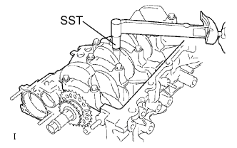
Tighten the bolts in several steps to the specified torque in the sequence shown in the illustration. (*1)
![]() |
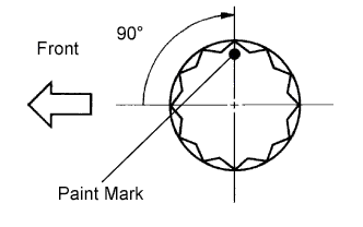
Mark the front of the bearing cap bolts with paint.
Retighten the bearing cap bolts by 90° in the same sequence as step (*1).
Check that the painted mark is now at a 90° angle from the front.
Remove the bearing cap sub-assembly.
![]() |
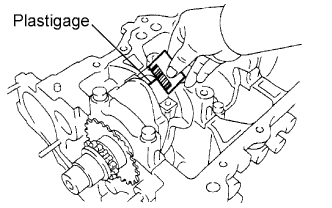
Measure the Plastigage at its widest point.
![]() |
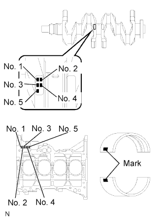
When replacing a standard bearing, replace it with one with the same number. If the number of the bearing cannot be found on the bearing shell, select the correct bearing by adding together the numbers imprinted on the cylinder block and crankshaft, then select the bearing with the same number as the total. There are 4 sizes of standard bearings, marked 1, 2, 3 and 4 accordingly.
| Cylinder Block (A) + Crankshaft (B) | 0 to 2 | 3 to 5 | 6 to 8 | 9 to 11 |
| Use Bearing | 1 | 2 | 3 | 4 |
| Item | Mark | mm (in.) |
| Cylinder block main journal bore diameter (A) | 0 1 2 3 4 5 6 | 50.000 to 50.003 (1.96850 to 1.96862) 50.003 to 50.005 (1.96862 to 1.96870) 50.005 to 50.007 (1.96870 to 1.96878) 50.007 to 50.010 (1.96878 to 1.96890) 50.010 to 50.012 (1.96890 to 1.96898) 50.012 to 50.014 (1.96898 to 1.96906) 50.014 to 50.016 (1.96906 to 1.96913) |
| Crankshaft main journal diameter (B) | 0 1 2 3 4 5 | 45.998 to 46.000 (1.81094 to 1.81102) 45.996 to 45.998 (1.81087 to 1.81094) 45.994 to 45.996 (1.81079 to 1.81087) 45.992 to 45.994 (1.81071 to 1.81079) 45.990 to 45.992 (1.81063 to 1.81071) 45.988 to 45.990 (1.81055 to 1.81063) |
| Standard bearing center wall thickness | 1 2 3 4 | 1.992 to 1.995 (0.07843 to 0.07854) 1.995 to 1.998 (0.07854 to 0.07866) 1.998 to 2.001 (0.07866 to 0.07878) 2.001 to 2.004 (0.07878 to 0.07890) |
| 10. INSTALL WITH PIN PISTON SUB-ASSEMBLY |
![]() |
Coat the piston pin and pin holes in the piston with engine oil.
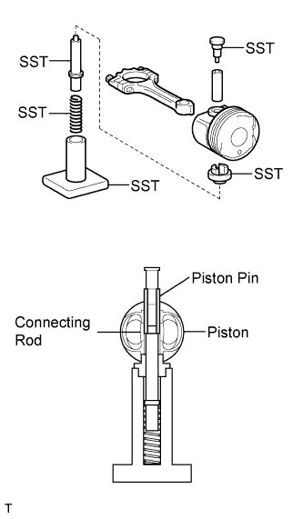
Align the cavity of the piston with the protruded portion on the connecting rod.
![]() |
Using SST, press in the piston pin.
| 11. INSTALL CONNECTING ROD BEARING |
![]() |
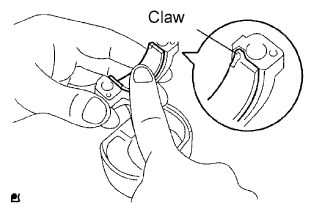
Align the bearing claw with the groove of the connecting rod or connecting cap.
| 12. INSTALL PISTON RING SET |
![]() |
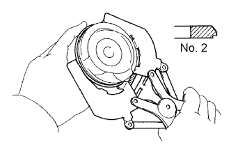
Install the oil ring expander and 2 side rails by hand.
Using a piston ring expander, install the 2 compression rings.
![]() |
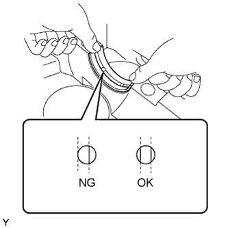
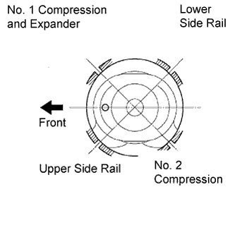
Position the piston rings so that the ring ends are as shown.
| 13. INSTALL PISTON SUB-ASSEMBLY WITH CONNECTING ROD |
Apply engine oil to the cylinder walls, the pistons, and the surfaces of connecting rod bearings.
Check the position of the piston ring ends.
![]() |
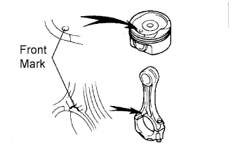
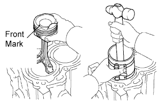
Using a piston ring compressor, push the correctly numbered piston and connecting rod assemblies into each cylinder with the front mark on the piston facing forward.
![]() |
Make sure that the connecting rod and its cap are in the correct combination and that the front mark of the cap is facing in the correct mounting orientation, then install the cap onto the connecting rod.
Apply a light coat of engine oil to the threads of the connecting rod cap bolts.
![]() |
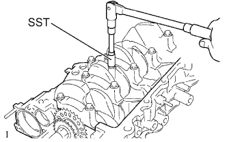
Using SST, tighten the bolts in several steps to the specified torque.
![]() |
Mark the front of the connecting cap bolts with paint.
Retighten the cap bolts by 90° as shown.
Check that the crankshaft turns smoothly.
| 14. INSPECT CONNECTING ROD THRUST CLEARANCE |
![]() |
Using a dial indicator, measure the thrust clearance while moving the connecting rod back and forth.
| 15. INSPECT CONNECTING ROD OIL CLEARANCE |
Check that the matchmarks on the connecting rod and cap are aligned to ensure correct reassembly.
![]() |
Using SST, remove the 2 connecting rod cap bolts.
Clean the crank pin and bearing.
Check the crank pin and bearing for pitting and scratches.
![]() |
Lay a strip of Plastigage across the crank pin.
![]() |
Make sure that the connecting rod and its cap are in the correct combination and that the front mark of the cap is facing in the correct mounting orientation, then install the cap onto the connecting rod.
Apply a light coat of engine oil to the threads of the connecting rod cap bolts.
![]() |
Using SST, tighten the bolts in several steps to the specified torque.
![]() |
Mark the front of the connecting cap bolts with paint.
Retighten the cap bolts by 90° as shown in the illustration.
Remove the 2 bolts, connecting rod cap and lower bearing.
![]() |
Measure the plastigage at its widest point.
![]() |
When replacing a bearing, replace it with one with the same number as marked on the connecting rod. There are 3 sizes of standard bearings, marked 1, 2 and 3 accordingly.
| Mark | mm (in.) |
| 1 | 1.491 to 1.494 (0.0587 to 0.0588) |
| 2 | 1.494 to 1.497 (0.0588 to 0.0589) |
| 3 | 1.497 to 1.500 (0.0589 to 0.0591) |
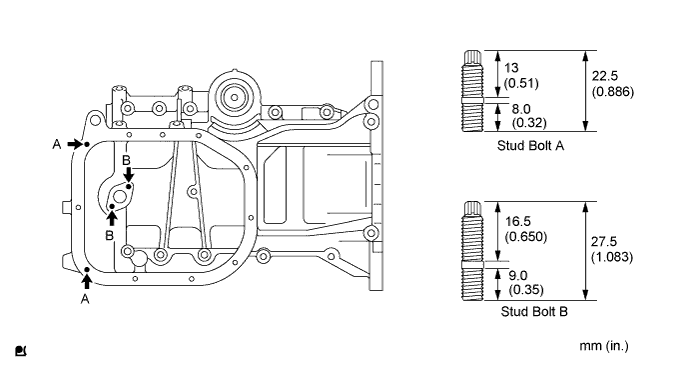
| 16. INSTALL STUD BOLT |
Using "Trox" socket wrench E5, install the 4 stud bolts.

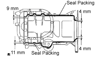
| 17. INSTALL OIL PAN SUB-ASSEMBLY |
Remove any old packing material from the contact surface.
![]() |
Apply a continuous bead of seal packing (Diameter 2.0 mm to 3.0 mm (0.079 to 0.118 in.)) to the oil pan mating surface as shown in the illustration.
Install 2 new O-rings onto the cylinder block.
![]() |
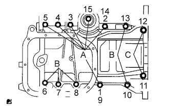
Using several steps, install and tighten the 13 bolts uniformly in the sequence shown in the illustration.
| 18. INSTALL OIL STRAINER SUB-ASSEMBLY |
Install a new gasket and the oil strainer with the 2 nuts and the bolt.
| 19. INSTALL OIL PAN SUB-ASSEMBLY NO. 2 |
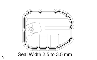
Remove any old packing material from the contact surface.
![]() |
Apply a continuous bead of seal packing (Diameter 2.5 to 3.5 mm (0.0984 to 0.1378 in.)) to the oil pan mating surface as shown in the illustration.
Install oil pan No. 2 with the 9 bolts and the 2 nuts.
Install the drain plug with a new gasket.
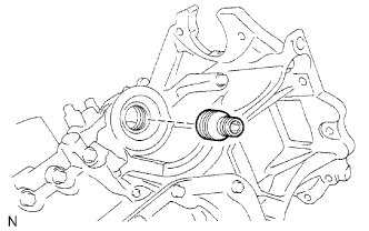
| 20. INSTALL OIL FILTER UNION |
![]() |
Using a 12 mm hexagon wrench, install the oil filter union.
| 21. INSTALL OIL FILTER SUB-ASSEMBLY |
Check and clean the oil filter installation surface.
Apply clean engine oil to the gasket of the new oil filter.
Gently screw the oil filter into place, and tighten it until the gasket comes into contact with the seat.
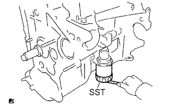
![]() |
Using SST, tighten it an additional 3/4 turn.
| 22. INSTALL CYLINDER HEAD GASKET |
![]() |
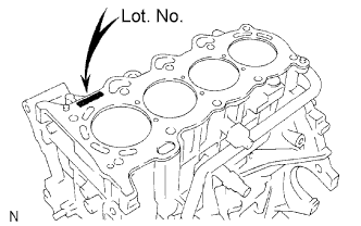
Place a new cylinder head gasket on the cylinder block with the Lot No. stamp facing upward.
| 23. INSTALL CYLINDER HEAD SUB-ASSEMBLY |
![]() |
Apply a light coat of engine oil to the threads of the cylinder head bolts.
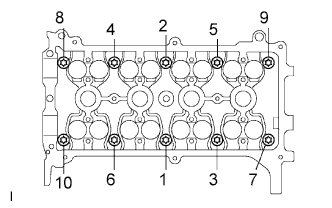
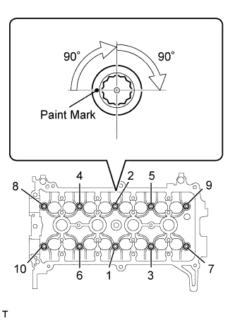
Using several steps, install and tighten the 10 cylinder head bolts and plate washers uniformly with an 8 mm bi-hexagon wrench in the sequence shown in the illustration.
Mark the front of the cylinder head bolt with paint.
![]() |
Retighten the cylinder head bolts by additional 90° and one more additional 90° as shown in the illustration.
Check that the paint mark is now at a 180° angle from the front.
![]() |
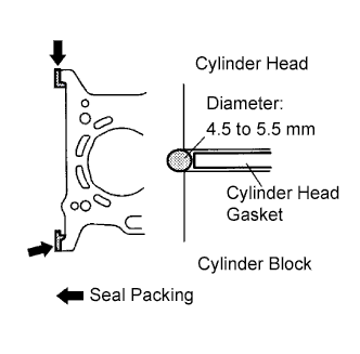
Apply a continuous bead of seal packing (Diameter 4.5 to 5.5 mm (0.177 to 0.217 in.)) as shown in the illustration.
| 24. INSTALL ENGINE REAR OIL SEAL |
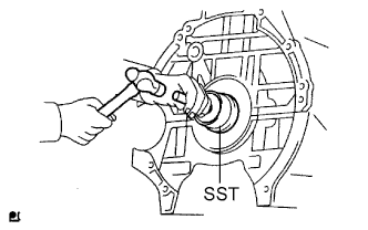
Apply MP grease to a new oil seal lip.
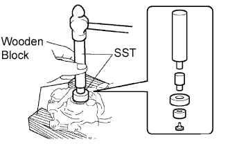
![]() |
Using SST and a hammer, tap in the oil seal until its surface is flush with the rear oil seal retainer edge.
| 25. INSTALL CAMSHAFT TIMING GEAR ASSEMBLY (for Unleaded Gasoline Specification Vehicle) |
![]() |
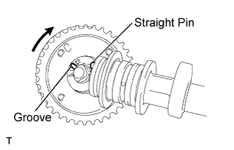
Put the camshaft timing gear assembly and camshaft together with the straight pin of the groove.
Turn the camshaft timing gear assembly clockwise while pushing it gently towards the camshaft. When the pin fits into the groove, push to ensure a good fit.
Check that there is no clearance between the gear flange and the camshaft.
Tighten the flange bolt with the camshaft timing gear fixed.
Check that the camshaft timing gear assembly can move in the retard direction (to the right) and is locked in the most retarded position.
| 26. INSTALL CAMSHAFT TIMING SPROCKET (for Leaded Gasoline Specification Vehicle) |
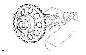
Clamp the camshaft in a vice.
![]() |
Align the knock pin hole in the camshaft timing sprocket with the knock pin of the camshaft, and install the camshaft timing sprocket.
| 27. INSTALL CAMSHAFT |
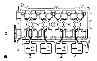
Apply a light coat of engine oil to the camshaft journals.
Place the camshaft on the cylinder head with the timing mark on the camshaft timing gear facing upward.
![]() |
Examine the front marks and numbers and tighten the bolts in the sequence shown in the illustration.
| 28. INSTALL CAMSHAFT TIMING SPROCKET |
![]() |
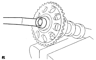
Clamp the camshaft in a vice.
Align the knock pin hole in the camshaft timing sprocket with the knock pin of the camshaft, and install the camshaft timing sprocket.
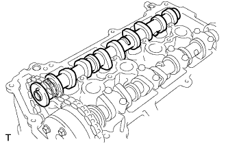
| 29. INSTALL NO. 2 CAMSHAFT |
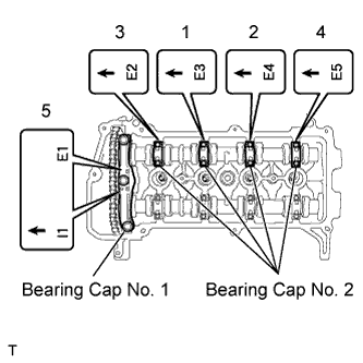
Apply a light coat of engine oil to the camshaft journals.
Place the camshaft on the cylinder head with the timing mark on the camshaft timing gear facing upward.
![]() |
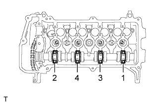
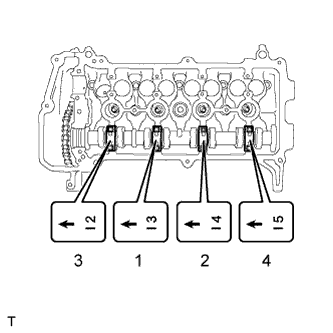
Examine the front marks and numbers on camshaft bearing cap No.1and No. 2 and check that the sequence order is as shown in the illustration. Then uniformly tighten the bolts, in several steps, in the sequence shown in the illustration.
| 30. INSTALL CAMSHAFT POSITION SENSOR |
![]() |
Apply engine oil to the O-ring.
Install the camshaft position sensor with the bolt.
| 31. INSTALL CHAIN SUB-ASSEMBLY |
![]() |
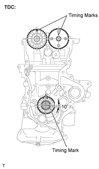
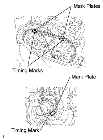
for Unleaded Gasoline Specification Vehicle:
Make sure that all the timing marks are in the positions (TDC) shown in the illustration.
![]() |
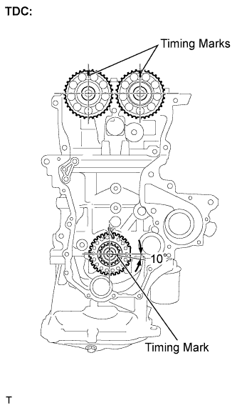
for Leaded Gasoline Specification Vehicle:
Make sure that each timing mark is in the position (TDC) shown in the illustration.
![]() |
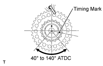
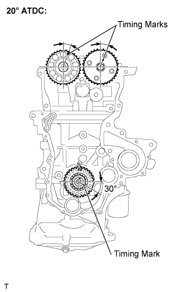
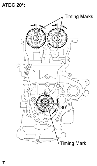
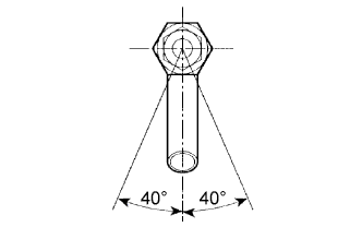
Set the timing mark of the crankshaft in a position between ATDC 40 and 140° from the TDC, as illustrated.
![]() |
for Unleaded Gasoline Specification Vehicle:
Set the camshaft timing gear and the camshaft timing sprocket in the positions (ATDC 20°) shown in the illustration.
for Unleaded Gasoline Specification Vehicle:
Set the crankshaft in the position (ATDC 20°) shown in the illustration.
![]() |
for Leaded Gasoline Specification Vehicle:
Set the camshaft timing sprockets in the position (ATDC 20°) shown in the illustration.
for Leaded Gasoline Specification Vehicle:
Set the crankshaft in the position (ATDC 20°) shown in the illustration.
![]() |
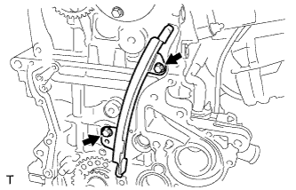
Install chain vibration damper No. 1 with the 2 bolts.
![]() |
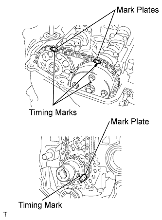
for Unleaded Gasoline Specification Vehicle:
Align the timing marks of the camshaft with the mark plates of the timing chain and install the timing chain.
![]() |
for Leaded Gasoline Specification Vehicle:
Align the timing marks of the camshaft with the mark plates of the timing chain and install the timing chain.
| 32. INSTALL CHAIN TENSIONER SLIPPER |
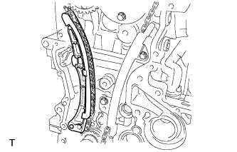
![]() |
Install the chain tensioner slipper.
| 33. INSTALL CHAIN TENSIONER ASSEMBLY NO. 1 |
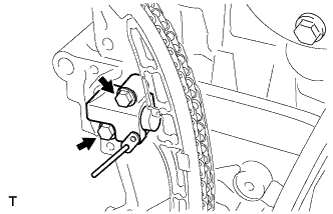
![]() |
Install chain tensioner assembly No. 1 with the 2 bolts.
Remove the bar from chain tensioner assembly No. 1.
| 34. INSTALL OIL PUMP SEAL |
![]() |
Using SST and a hammer, tap in a new oil seal until its surface is flush with the timing chain cover edge.
Apply MP grease to the oil seal lip.
| 35. INSTALL OIL PUMP ASSEMBLY |
![]() |
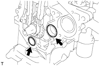
Install 2 new O-rings onto the 2 locations shown in the illustration.
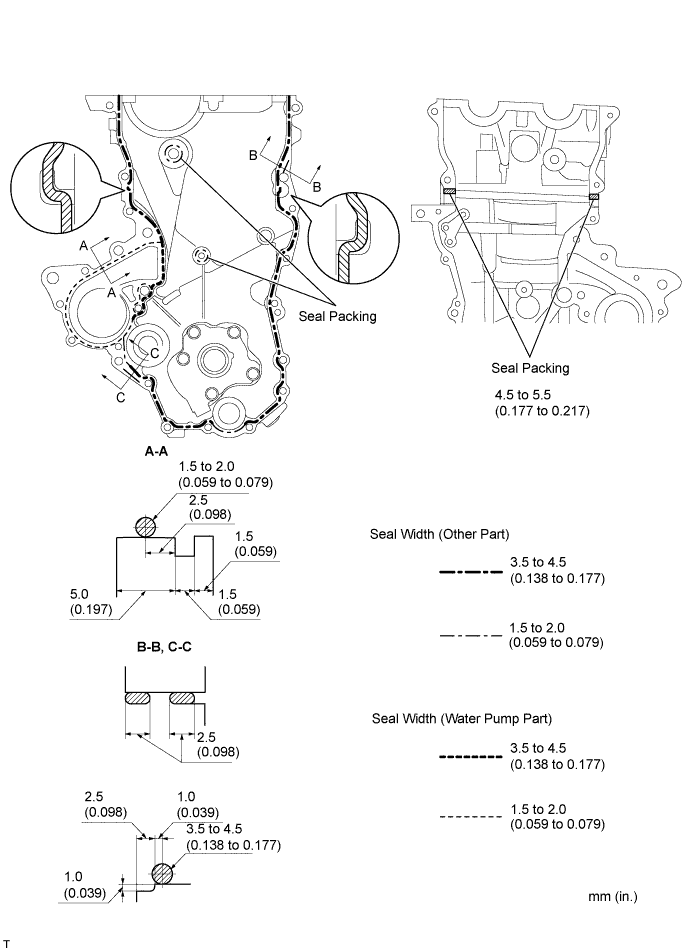
Apply seal packing to the oil pump assembly, cylinder head and cylinder block as shown in the illustration.

![]() |
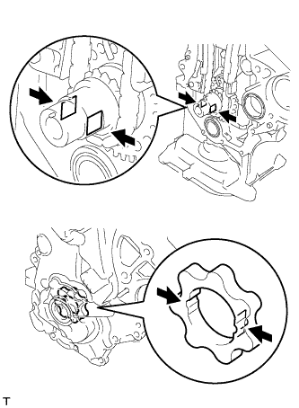
Align the keyway of the oil pump rotor with the rectangular portion of the crankshaft, and slide the oil pump into place.
![]() |
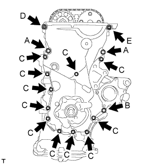
Install the oil pump assembly with the 15 bolts and nut. Tighten the bolts and nut uniformly in several steps.
| 36. INSTALL WATER PUMP ASSEMBLY |
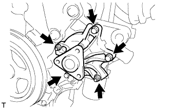
![]() |
Install the water pump and a new gasket with the 3 bolts and 2 nuts.
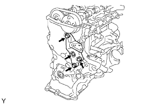
| 37. INSTALL TRANSVERSE ENGINE ENGINE MOUNTING BRACKET |
![]() |
Install the transverse engine mounting bracket with the 4 bolts.
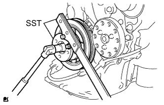
| 38. INSTALL CRANKSHAFT DAMPER SUB-ASSEMBLY |
Align the pin hole in the crankshaft damper with the pin position and install the crankshaft damper sub-assembly.
Provisionally install the bolt.
![]() |
Using 2 SSTs, tighten the bolt while holding the crankshaft damper sub-assembly.
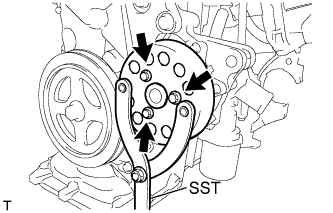
| 39. INSTALL WATER PUMP PULLEY |
![]() |
Using SST, install the pump pulley with the 3 bolts.
| 40. INSPECT VALVE CLEARANCE |
![]() |
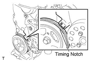
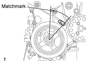
Set No. 1 cylinder to TDC/compression.
Turn the crankshaft damper, and align its timing notch with the timing mark "0" of the oil pump.
![]() |
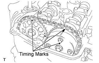
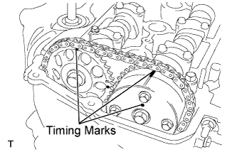
for Unleaded Gasoline Specification Vehicle:
Check that the timing marks on the camshaft timing sprocket and camshaft timing gear are all facing upward, as shown in the illustration.
![]() |
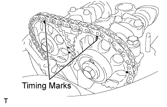
for Leaded Gasoline Specification Vehicle:
Check that both timing marks on the camshaft timing sprockets are facing upward as shown in the illustration.
![]() |
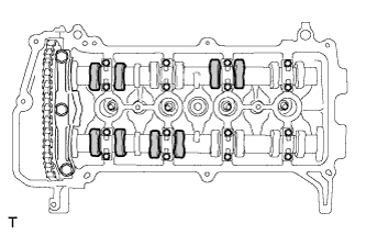
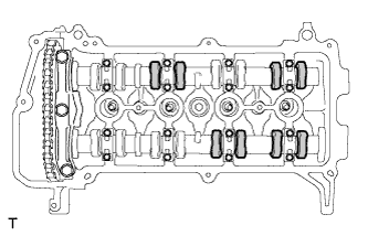
Check the valves indicated in the illustration.
Using a feeler gauge, measure the clearance between the valve lifter and camshaft.
Record any out-of-specification valve clearance measurements. They will be used later to determine the required replacement adjusting shim.
Turn the crankshaft 1 complete revolution (360°) and align its timing notch with timing mark "0" of the oil pump.
![]() |
Check the valves indicated in the illustration.
Using a feeler gauge, measure the clearance between the valve lifter and camshaft.
Record any out-of-specification valve clearance measurements. They will be used later to determine the required replacement adjusting shim.
| 41. ADJUST VALVE CLEARANCE |
![]() |
![]() |
Set No. 1 cylinder to TDC/compression.
Turn the crankshaft damper, and align its timing notch with timing mark "0" of the oil pump.
![]() |
for Unleaded Gasoline Specification Vehicle:
Check that the timing marks on the camshaft timing sprocket and camshaft timing gear are all facing upward, as shown in the illustration.
![]() |
for Leaded Gasoline Specification Vehicle:
Check that both timing marks on the camshaft timing sprockets facing upward as shown in the illustration.
![]() |
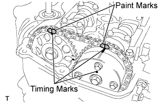
for Unleaded Gasoline Specification Vehicle:
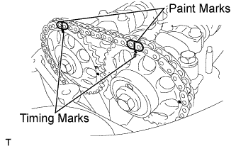
Put paint marks on the chain in place where the timing marks of the camshaft timing sprocket and the camshaft timing gear are located.
![]() |
for Leaded Gasoline Specification Vehicle:
Put paint marks on the chain in place where the timing marks of the camshaft timing sprockets.
![]() |
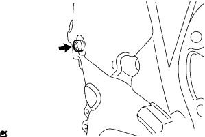
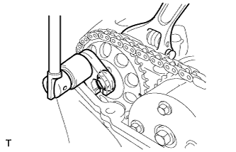
Using an 8 mm hexagon wrench, remove the screw plug.
![]() |
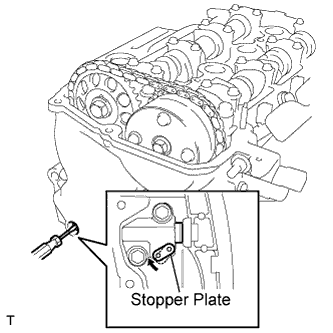
Insert a screwdriver into the service hole in the chain tensioner to pull the stopper plate of the chain tensioner upward.
![]() |
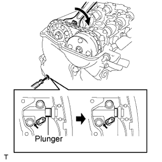
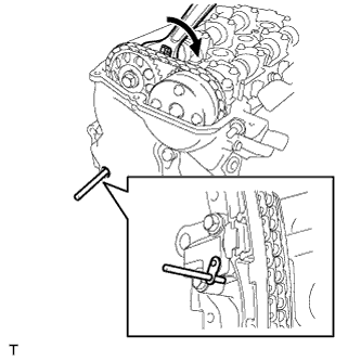
Using a wrench, rotate No. 2 camshaft clockwise to push in the plunger of the chain tensioner.
![]() |
Remove the screwdriver from the service hole, then align the hole in the stopper plate with the service hole and insert a 3 mm (0.12 in.) diameter bar into the holes to hold the stopper plate.
![]() |
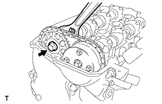
Using a wrench, hold the hexagonal lobe of No. 2 camshaft and remove the flange bolt.
![]() |
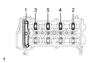
Using several steps, loosen and remove the 11 bearing cap bolts uniformly in the sequence shown in the illustration, then remove camshaft bearing cap No. 1 and camshaft bearing cap No. 2.
![]() |
Remove the flange bolt and remove the camshaft timing sprocket.
![]() |
Remove No. 2 camshaft.
![]() |
Using several steps, loosen and remove the 8 bearing cap bolts uniformly in the sequence shown in the illustration, then remove camshaft bearing cap No. 2.
![]() |
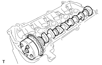
for Unleaded Gasoline Specification Vehicle:
Hold the chain by hand, and remove the camshaft and the camshaft timing gear assembly.
![]() |
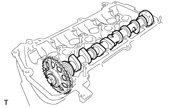
for Leaded Gasoline Specification Vehicle:
Hold the chain by hand, and remove the camshaft and the camshaft timing sprocket.
![]() |
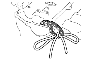
Tie the chain with a piece of string as shown in the illustration.
Remove the valve lifters.
![]() |
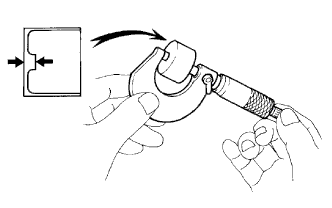
Using a micrometer, measure the thickness of the removed lifter.
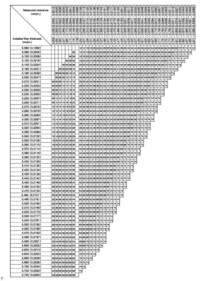
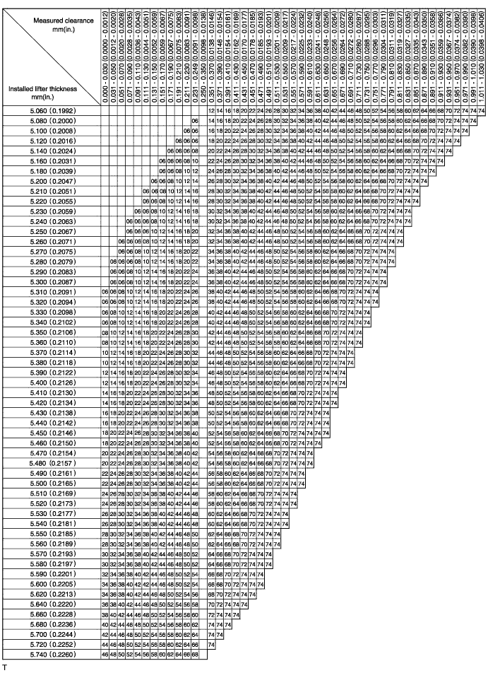
Calculate the thickness of a new lifter so that the valve clearance comes to within the specified values.
| A | Thickness of new lifter |
| B | Thickness of used lifter |
| C | Measured valve clearance |
Select a new lifter with the thickness as close to the calculated values as possible.

| Shim No. | Thickness | Shim No. | Thickness | Shim No. | Thickness |
| 06 | 5.060 (0.1992) | 30 | 5.300 (0.2087) | 54 | 5.540 (0.2181) |
| 08 | 5.080 (0.2000) | 32 | 5.320 (0.2094) | 56 | 5.560 (0.2189) |
| 10 | 5.100 (0.2008) | 34 | 5.340 (0.2102) | 58 | 5.580 (0.2197) |
| 12 | 5.120 (0.2016) | 36 | 5.360 (0.2110) | 60 | 5.600 (0.2205) |
| 14 | 5.140 (0.2024) | 38 | 5.380 (0.2118) | 62 | 5.620 (0.2213) |
| 16 | 5.160 (0.2031) | 40 | 5.400 (0.2126) | 64 | 5.640 (0.2220) |
| 18 | 5.180 (0.2039) | 42 | 5.420 (0.2134) | 66 | 5.660 (0.2228) |
| 20 | 5.200 (0.2047) | 44 | 5.440 (0.2142) | 68 | 5.680 (0.2236) |
| 22 | 5.220 (0.2055) | 46 | 5.460 (0.2150) | 70 | 5.700 (0.2244) |
| 24 | 5.240 (0.2063) | 48 | 5.480 (0.2157) | 72 | 5.720 (0.2252) |
| 26 | 5.260 (0.2071) | 50 | 5.500 (0.2165) | 74 | 5.740 (0.2260) |
| 28 | 5.280 (0.2079) | 52 | 5.520 (0.2173) |

| Shim No. | Thickness | Shim No. | Thickness | Shim No. | Thickness |
| 06 | 5.060 (0.1992) | 30 | 5.300 (0.2087) | 54 | 5.540 (0.2181) |
| 08 | 5.080 (0.2000) | 32 | 5.320 (0.2094) | 56 | 5.560 (0.2189) |
| 10 | 5.100 (0.2008) | 34 | 5.340 (0.2102) | 58 | 5.580 (0.2197) |
| 12 | 5.120 (0.2016) | 36 | 5.360 (0.2110) | 60 | 5.600 (0.2205) |
| 14 | 5.140 (0.2024) | 38 | 5.380 (0.2118) | 62 | 5.620 (0.2213) |
| 16 | 5.160 (0.2031) | 40 | 5.400 (0.2126) | 64 | 5.640 (0.2220) |
| 18 | 5.180 (0.2039) | 42 | 5.420 (0.2134) | 66 | 5.660 (0.2228) |
| 20 | 5.200 (0.2047) | 44 | 5.440 (0.2142) | 68 | 5.680 (0.2236) |
| 22 | 5.220 (0.2055) | 46 | 5.460 (0.2150) | 70 | 5.700 (0.2244) |
| 24 | 5.240 (0.2063) | 48 | 5.480 (0.2157) | 72 | 5.720 (0.2252) |
| 26 | 5.260 (0.2071) | 50 | 5.500 (0.2165) | 74 | 5.740 (0.2260) |
| 28 | 5.280 (0.2079) | 52 | 5.520 (0.2173) |
Install the selected valve lifter.
Apply a light coat of engine oil to the camshaft and camshaft journals.
![]() |
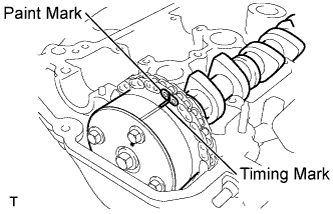
for Unleaded Gasoline Specification Vehicle:
Install the chain onto the camshaft timing gear with the paint mark and the timing mark aligned, as shown in the illustration.
![]() |
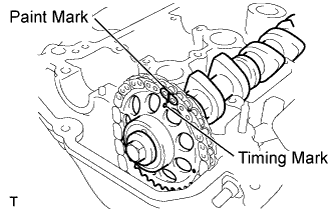
for Leaded Gasoline Specification Vehicle:
Install the chain onto the camshaft timing sprocket with the paint mark and the timing mark aligned as shown in the illustration.
![]() |
Examine the front marks and the numbers on camshaft bearing cap No. 2 and check that the sequence is as shown in the illustration. Then uniformly tighten the bolts in several steps in the sequence shown in the illustration.
![]() |
Install camshaft No. 2.
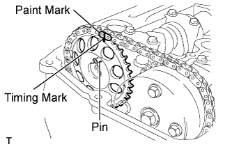
![]() |
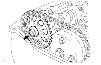
Hold the chain, and align the timing mark on the camshaft timing sprocket with paint mark of the chain.
Align the alignment pin hole in the camshaft timing sprocket with the alignment pin of the camshaft, and install the sprocket onto the camshaft.
![]() |
Provisionally install the flange bolt.
![]() |
Examine the front marks and the numbers of camshaft bearing cap No. 1 and camshaft bearing cap No. 2 and check that the sequence is as shown in the illustration. Then uniformly tighten the bolts, in several steps, in the sequence shown in the illustration.
![]() |
Using a union nut wrench, hold the hexagonal lobe of camshaft No. 2, and install the flange bolt.
Remove the bar from the timing chain tensioner.
![]() |
Turn the crankshaft damper, and align its timing notch with timing mark "0" of the oil pump.
![]() |
for Unleaded Gasoline Specification Vehicle:
Check that all the pairs of timing marks are aligned.
![]() |
for Leaded Gasoline Specification Vehicle:
Check that all the pairs of the timing marks are aligned.
Apply adhesive to the end 2 or 3 threads of the screw plug.
![]() |
Using an 8 mm hexagon wrench, install the screw plug.
| 42. INSTALL CAMSHAFT TIMING OIL CONTROL VALVE ASSEMBLY (for Unleaded Gasoline Specification Vehicle) |
![]() |
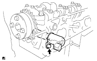
Apply a light coat of engine oil to a new O-ring, and install it onto the camshaft timing oil control valve.
Install the camshaft timing oil control valve with the bolt.
| 43. INSTALL FUEL INJECTOR ASSEMBLY |
![]() |
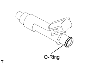
Apply a light coat of gasoline or spindle oil to new O-rings, then install one onto each fuel injector.
Apply a light coat of gasoline or spindle oil to the contact surfaces of the fuel delivery pipe and the O-ring of the fuel injector.
![]() |
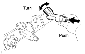
While turning the fuel injector left and right, install it onto the fuel delivery pipe.
| 44. INSTALL INJECTOR VIBRATION INSULATOR |
![]() |
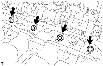
Install 4 new injector vibration insulators onto the cylinder head.
| 45. INSTALL DELIVERY PIPE NO. 1 SPACER |
![]() |
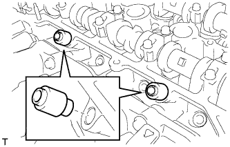
Install the 2 delivery pipe No. 1 spacers onto the cylinder head.
| 46. INSTALL FUEL DELIVERY PIPE SUB-ASSEMBLY |
![]() |
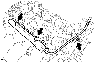
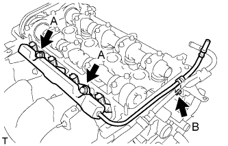
Provisionally install the fuel delivery pipe sub-assembly with the 4 fuel injectors using the 3 bolts.
![]() |
Tighten the 3 bolts to the specified torque.
| 47. INSTALL CYLINDER HEAD COVER SUB-ASSEMBLY |
![]() |
Install the gasket onto the cylinder head cover.
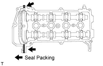
Apply seal packing to the cylinder head, as shown in the illustration.
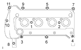
Install the cylinder head cover sub-assembly with the 9 bolts, 2 nuts and 2 seal washers.
![]() |
Tighten the 9 bolts and 2 nuts in the sequence shown in the illustration.
| 48. INSTALL VENTILATION VALVE SUB-ASSEMBLY |
![]() |
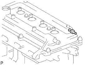
Install the ventilation valve onto the cylinder head cover.
| 49. INSTALL OIL LEVEL GAUGE GUIDE |
Apply engine oil to a new O-ring.
Install the oil level gauge guide with the bolt.
| 50. INSTALL CRANKSHAFT POSITION SENSOR |
Apply a light coat of engine oil to the O-ring on the crankshaft position sensor.
Install the crankshaft position sensor with the bolt.
| 51. INSTALL OIL FILLER CAP GASKET |
Install the oil filler cap gasket onto the oil filler cap.
| 52. INSTALL OIL FILLER CAP SUB-ASSEMBLY |
Install the oil filler cap onto the cylinder head cover.
| 53. INSTALL THERMOSTAT |
Install a new gasket onto the thermostat.
![]() |
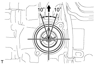
Install the thermostat with the jiggle valve facing upward.
| 54. INSTALL WATER INLET |
![]() |
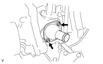
Install the water inlet with radiator hose using the 2 nuts.
| 55. INSTALL ENGINE COOLANT TEMPERATURE SENSOR |
Provisionally install the engine coolant temperature sensor through a new gasket.
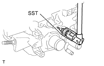
![]() |
Using SST, tighten the engine coolant temperature sensor.
| 56. INSTALL ENGINE OIL PRESSURE SWITCH ASSEMBLY |
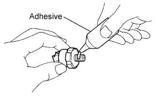
![]() |
Apply adhesive to the end 2 or 3 threads of the oil pressure switch.
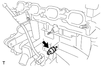
![]() |
Using a 24 mm deep socket wrench, install the oil pressure switch.
| 57. INSTALL KNOCK SENSOR |
![]() |
Install the knock sensor with the nut as shown in the illustration.
| 58. INSTALL SPARK PLUG |
![]() |
Using a spark plug wrench, install the spark plugs.