 |
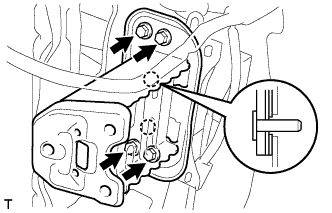
Install the front bumper arm with the 4 bolts.
- Torque:
- 40 N*m{ 410 kgf*cm , 30 ft.*lbf }
FRONT BUMPER (for Hatchback) > INSTALLATION |
| 1. INSTALL FRONT BUMPER ARM SUB-ASSEMBLY LH |
|
Install the front bumper arm with the 4 bolts.
| 2. INSTALL FRONT BUMPER ARM SUB-ASSEMBLY RH |
| 3. INSTALL WINDSHIELD WASHER JAR ASSEMBLY |
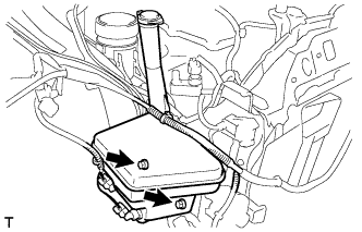 |
Install the windshield washer jar with the 2 bolts.
| 4. INSTALL FRONT BUMPER STONE DEFLECTOR BRACKET (w/o Radiator Support Extension) |
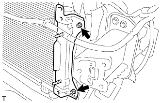 |
Install the front bumper stone deflector bracket with the 2 nuts.
| 5. INSTALL FRONT BUMPER STONE DEFLECTOR BRACKET (w/ Radiator Support Extension) |
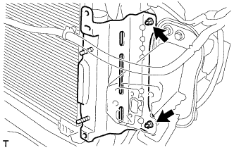 |
Install the front bumper stone deflector bracket with the 2 nuts.
| 6. INSTALL FRONT BUMPER REINFORCEMENT SUB-ASSEMBLY |
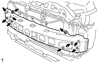 |
Install the front bumper reinforcement with the 4 nuts and the 6 bolts.
| 7. INSTALL NO. 2 ENGINE ROOM WIRE (w/ Fog Light) |
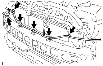 |
Install the 6 clamps.
| 8. INSTALL NO. 2 ENGINE ROOM WIRE (w/o Fog Light) |
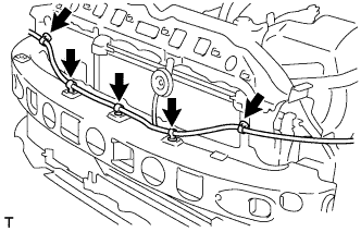 |
Install the 5 clamps.
| 9. INSTALL RADIATOR SUPPORT EXTENSION LH (w/ Radiator Support Extension) |
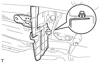 |
Engage the 2 claws and install the radiator support extension.
| 10. INSTALL RADIATOR SUPPORT EXTENSION RH (w/ Radiator Support Extension) |
| 11. INSTALL THERMISTOR ASSEMBLY |
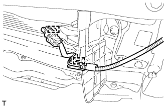 |
Engage the 2 clamps and install the thermistor.
| 12. INSTALL RADIATOR SIDE AIR SEAL LH (w/o Radiator Support Extension) |
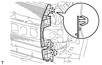 |
Engage the 3 claws and install the radiator side air seal.
| 13. INSTALL RADIATOR SIDE AIR SEAL RH (w/o Radiator Support Extension) |
| 14. INSTALL RADIATOR SIDE AIR SEAL LH (w/ Radiator Support Extension) |
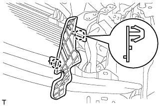 |
Engage the 2 claws and install the radiator side air seal.
| 15. INSTALL RADIATOR SIDE AIR SEAL RH (w/ Radiator Support Extension) |
| 16. INSTALL FRONT BUMPER LOWER ABSORBER (w/ Front Bumper Lower Absorber) |
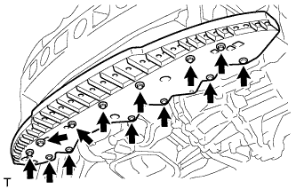 |
Install the front bumper lower absorber with the 4 screws.
Install the 6 clips.
| 17. INSTALL ENGINE UNDER COVER RH |
| 18. INSTALL ENGINE UNDER COVER LH |
| 19. INSTALL ENGINE UNDER COVER SUB-ASSEMBLY (for Rough Road Area Specification Vehicles) |
| 20. INSTALL RADIATOR SUPPORT UPPER ABSORBER |
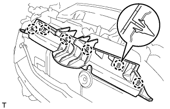 |
Engage the 6 claws and install the radiator support upper absorber.
| 21. INSTALL FRONT BUMPER SIDE RETAINER LH |
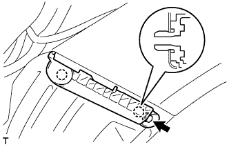 |
Engage the 2 claws and install the front bumper side retainer.
Tighten the screw.
| 22. INSTALL FRONT BUMPER SIDE RETAINER RH |
| 23. INSTALL HEADLIGHT ASSEMBLY LH |
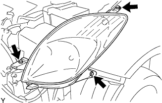 |
w/ Headlight leveling:
Connect the 4 connectors.
w/o Headlight leveling:
Connect the 3 connectors.
Install the headlight with the 3 screws.
| 24. INSTALL HEADLIGHT ASSEMBLY RH |
| 25. INSTALL FRONT BUMPER COVER |
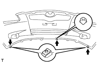 |
Install the 2 clips and the screw grommet.
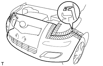 |
Engage the 6 claws and install the front bumper cover.
Connect the 2 connectors.
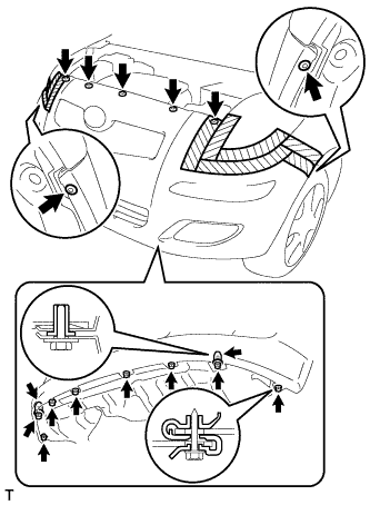 |
Install the 7 clips.
Install the 2 screw grommets.
Tighten the 8 screws.
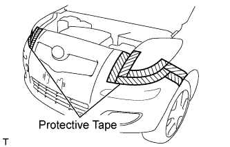 |
Remove the protective tape.
| 26. PREPARE VEHICLE FOR HEADLIGHT AIMING ADJUSTMENT |
Prepare the vehicle:
| 27. PREPARE FOR HEADLIGHT AIMING (for Using a Screen) |
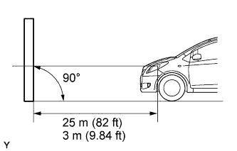 |
Prepare the vehicle in accordance with the following conditions:
Prepare a piece of thick white paper (approximately 2 m (6.6 ft) high x 4 m (13.1 ft) wide) to use as a screen.
Draw a vertical line down the center of the screen (V line).
Set the screen, as shown in the illustration.
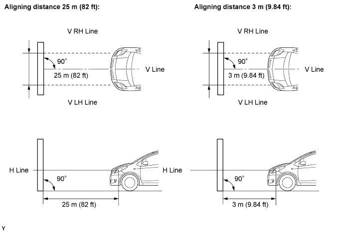
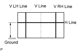 |
Draw base lines (H line, V LH and V RH lines) on the screen, as shown in the illustration.
H Line (Headlight height):
Draw a horizontal line across the screen so that it passes through the center marks. The H line should be at the same height as the headlight bulb center marks of the low-beam headlights.
V LH Line and V RH Line (Center mark positions of left-hand (LH) and right-hand (RH) headlights):
Draw two vertical lines so that they intersect the H line at each center mark (aligned with the center of the low-beam headlight bulbs).
| 28. INSPECT HEADLIGHT AIMING |
Cover the headlight on the opposite side or disconnect its connector, to prevent light from the headlight not being inspected from affecting the headlight aiming inspection.
Start the engine.
w/ Headlight leveling:
Set the headlight leveling switch to 0 (zero).
Turn on the headlight and make sure that the cutoff line falls within the specified area, as shown in the illustration.
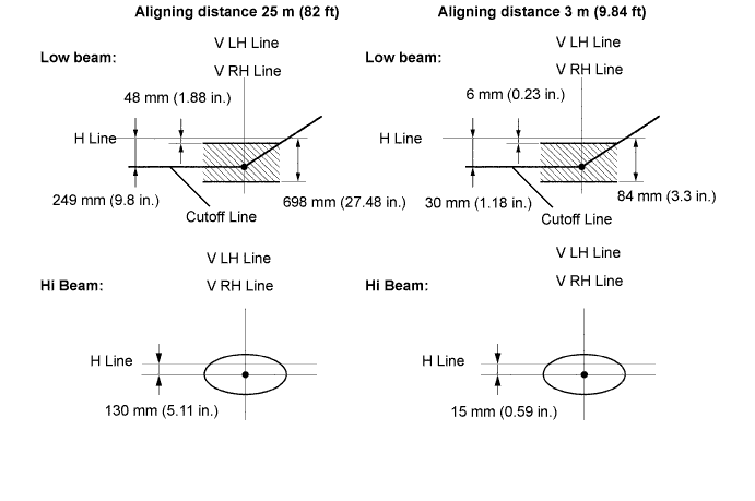
| 29. ADJUST HEADLIGHT AIMING |
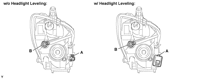
Adjust the aiming vertically:
Adjust the headlight aim to within the specified range by turning aiming screw A with a screwdriver.
Perform low-beam aim adjustment.
Adjust the aim horizontally:
Adjust the headlight aim to within the specified range by turning aiming screw B with a screwdriver.
| 30. PREPARE VEHICLE FOR FOG LIGHT AIMING ADJUSTMENT |
Prepare the vehicle:
| 31. PREPARE FOR FOG LIGHT AIMING |
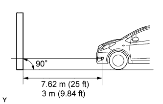 |
Prepare the vehicle in accordance with the following conditions:
Prepare a piece of thick white paper (approximately 2 m (6.6 ft) (high) x 4 m (13.1 ft) (wide)) to use as a screen.
Draw a vertical line down the center of the screen (V line).
Set the screen as shown in the illustration.
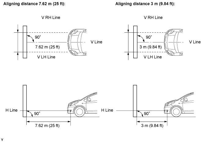
|
Draw base lines (H line, V LH, V RH lines) on the screen as shown in the illustration.
H Line (Fog light height):
Draw a horizontal line across the screen so that it passes through the center marks. The H line should be at the same height as the fog light bulb center marks of the low-beam fog lights.
V LH Line and V RH Line (Center mark positions of left-hand (LH) and right-hand (RH) fog lights):
Draw two vertical lines so that they intersect the H line at each center mark.
| 32. INSPECT FOG LIGHT AIMING |
Cover the fog light or disconnect the connector of the fog light on the opposite side to prevent light from the fog light not being inspected from affecting fog light aiming inspection.
Start the engine.
Turn on the fog light and make sure that the cutoff line falls within the specified area, as shown in the illustration.
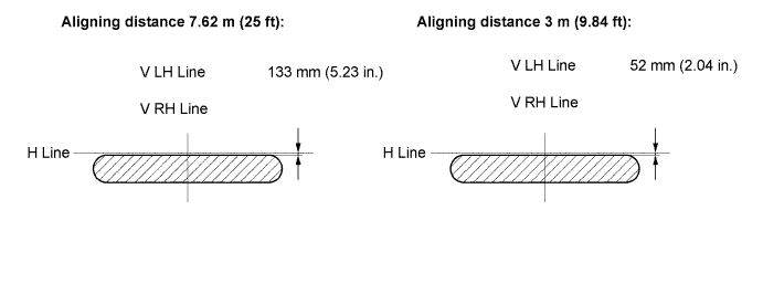
| 33. ADJUST FOG LIGHT AIMING |
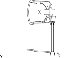 |
Adjust the fog light aim to within the specified range by turning the aiming screw with a screwdriver.