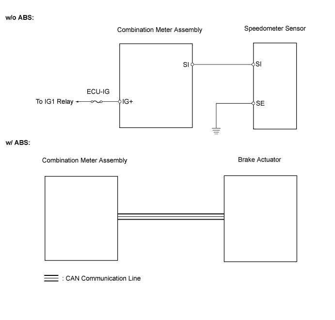
METER / GAUGE SYSTEM (for Sedan) > Speedometer Malfunction |
| 1.PERFORM ACTIVE TEST USING INTELLIGENT TESTER (SPEED METER) |
Connect the intelligent tester to the DLC3.
Turn the ignition switch ON and turn the tester on.
Perform the Active Test according to the prompts displayed on the tester.
| Item | Test Details | Diagnostic Note |
| Speed Meter Operation | 0 / 40 (24) / 80 (48) / 120 (72) / 160 (96) / 200 (120) / 240 (144) km / (mph) | - |
|
| ||||
| OK | |
 |
| 2.CHECK BRAKE CONTROL SYSTEM |
Check the brake control system.
| Brake Control System | Proceed to |
| w/ ABS | A |
| w/o ABS | B |
|
| ||||
| A | |
|
| 3.READ VALUE USING INTELLIGENT TESTER (VEHICLE SPEED METER) |
Connect the intelligent tester to the DLC3.
Turn the ignition switch ON and turn the tester on.
Read the Data List according to the prompts displayed on the tester.
| Item | Measurement Item / Range (Display) | Normal Condition | Diagnostic Note |
| Vehicle Speed Meter | Vehicle speed / Min.: 0 km/h (0mph), Max.: 255 km/h (158mph) | Approximately same as actual vehicle speed (When vehicle is driven) | - |
|
| ||||
| OK | ||
 | ||
| ||
| 4.INSPECT SPEEDOMETER SENSOR |
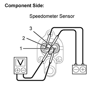 |
Remove the speedometer sensor.
Connect the positive (+) lead from the battery to terminal 1 and the negative(-) lead to terminal 2.
Connect the positive (+) lead from the tester to terminal 3 and the negative (-) lead to terminal 2.
Rotate the shaft.
Check that the voltage output between terminals 2 and 3 varies between 0V and 11V.
Reinstall the speedometer sensor.
|
| ||||
| OK | |
|
| 5.CHECK HARNESS AND CONNECTOR (SPEEDOMETER SENSOR - COMBINATION METER ASSEMBLY) |
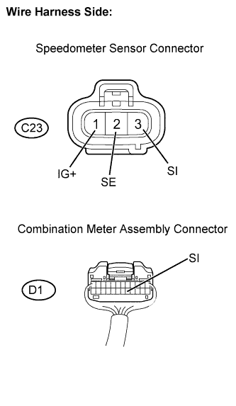 |
Disconnect the D1 combination meter assembly connector.
Disconnect the C23 speedometer sensor connector.
Measure the resistance.
| Tester Connection | Specified Condition |
| D1-17 (SI) - C23-3 (SI) | Below 1 Ω |
| C23-2 (SE) - Body ground | Below 1 Ω |
Reconnect the combination meter assembly connector.
Measure the voltage.
| Tester Connection | Condition | Specified Condition |
| C23-1 (IG+) - Body ground | Ignition switch ON | 10 to 14V |
Reconnect the speedometer sensor connector.
|
| ||||
| OK | ||
| ||
| ||

