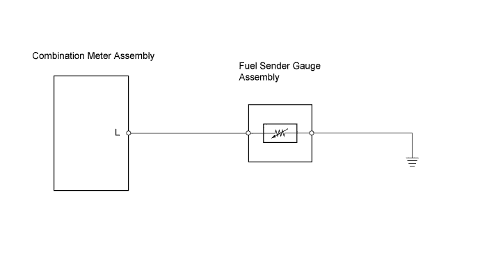
METER / GAUGE SYSTEM (for Sedan) > Fuel Gauge Malfunction |
| 1.PERFORM ACTIVE TEST USING INTELLIGENT TESTER (FUEL METER) |
Connect the intelligent tester to the DLC3.
Turn the ignition switch ON and turn the tester on.
Perform the Active Test according to the prompts displayed on the tester.
| Item | Test Details | Diagnostic Note |
| Fuel Meter Operation | EMPTY: Segment No. 1 flashes 1/2: Segment No. 1 to No. 4 illuminate FULL: Segment No. 1 to No. 8 illuminate | - |
|
| ||||
| OK | |
 |
| 2.READ VALUE USING INTELLIGENT TESTER (FUEL INPUT) |
Connect the intelligent tester to the DLC3.
Turn the ignition switch ON and turn the tester on.
Read the Data List according to the prompts displayed on the tester.
| Item | Measurement Item/Range (Display) | Normal Condition | Diagnostic Note |
| Fuel Input (A/D) | Fuel input signal / Min.: 0, Max.: 255 | Fuel receiver gauge segments No.1 to No.8 illuminate: 14 to 34 No.1 to (No.6, No.7) illuminate: 77 to 109 No.1 to (No.4, No,5) illuminate: 135 to 172 No.1 to No.2 illuminate: 175 to 188 No.1 flashes: 194 to 200 | - |
|
| ||||
| OK | |
|
| 3.CHECK COMBINATION METER ASSEMBLY |
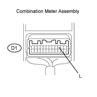 |
Disconnect the J5 fuel sender gauge assembly connector.
Remove the combination meter assembly with its connectors connected.
Measure the voltage.
| Tester Connection | Condition | Specified Condition |
| D1-3 (L) - Body ground | Ignition switch ON | 10 to 14 V |
Reconnect the fuel sender gauge assembly connector.
Reinstall the combination meter assembly.
|
| ||||
| OK | |
|
| 4.INSPECT FUEL SENDER GAUGE ASSEMBLY |
Type A:
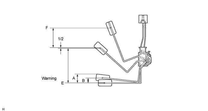
Remove the fuel sender gauge assembly.
Check that the float position is between E and F.
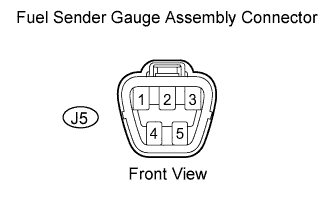 |
Measure the resistance between terminals 2 and 1 of the J5 fuel sender gauge assembly connector.
| Float Level | Float Position (mm (in.)) | Specified Condition |
| F | 77.3 (3.04) to 79.3 (3.12) | 15 Ω to 18 Ω |
| 1/2 | 1.6 (0.05) | 208.3 Ω |
| Warning A | 34.8 (1.37) | 365.2 Ω |
| Warning B | 25.3 (1.00) | 388.2 Ω |
| E | 75.0 (2.96) | 410.0 Ω |
Reinstall the fuel sender gauge assembly.
Type B:
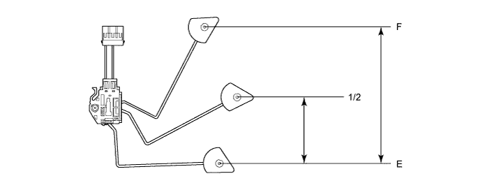
Remove the fuel sender gauge assembly.
Check that the float position is between E and F.
|
Measure the resistance between terminals 2 and 1 of the J5 fuel sender gauge assembly connector.
| Float Level | Float Position (mm (in.)) | Specified Condition |
| F | 146.2 (5.76) to 158.2 (6.23) | 13.5 to 16.5 Ω |
| 1/2 | 76.4 (3.01) to 88.4 (3.48) | 195.3 to 221.3 Ω |
| E | 0 (0) | 405.5 to 414.5 Ω |
Reinstall the fuel sender gauge assembly.
|
| ||||
| OK | |
|
| 5.CHECK HARNESS AND CONNECTOR (COMBINATION METER ASSEMBLY - FUEL SENDER GAUGE ASSEMBLY) |
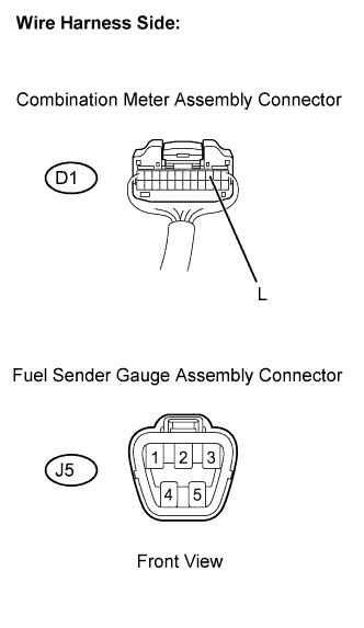 |
Disconnect the D1 combination meter assembly connector.
Disconnect the J5 fuel sender gauge assembly connector.
Measure the resistance.
| Tester Connection | Specified Condition |
| D1-3 (L) - J5-2 | Below 1Ω |
| J5-3 - Body ground | Below 1Ω |
Reconnect the combination meter assembly and fuel sender gauge assembly connectors.
|
| ||||
| OK | ||
 | ||
| ||
