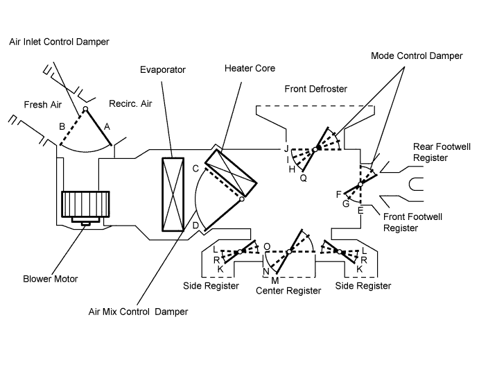
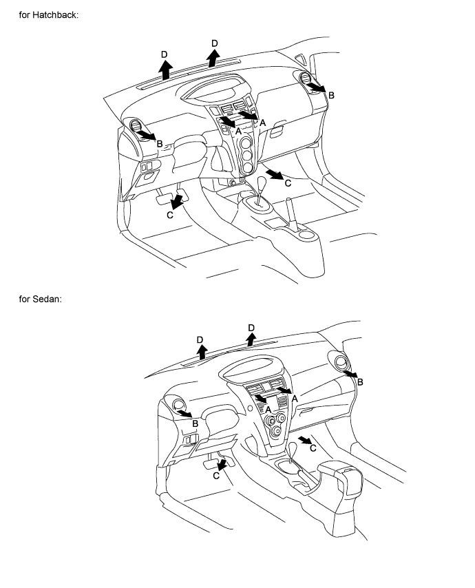
Control Damper
| Control Position
| Damper Position
| Operation
|
Air Inlet Control Damper
| FRESH
| A
| Allows outside air to enter.
|
RECIRC
| B
| Recirculates internal air.
|
Air Mix Control Damper
| COOL to HOT
| C, D
| Continuously changes mix ratio of warm and cool air between COOL and HOT.
|
Mode Control Damper
| FACE

| M, L, E, J
| Blows air from center register and side registers.
|
BI-LEVEL

| N, R, F, J
| Blows air from center register, side registers, front footwell register, and rear footwell register.
|
FOOT

| O, K, F, I
| Blows air from side registers, front footwell register, and rear footwell register. Also, blows some air from front defroster.
|
FOOT/DEF

| O, K, G, H
| Blows air from front defroster, side registers, front footwell register, and rear footwell register.
|
DEF

| O, R, E, Q
| Blows air from front defroster and side registers.
|