AUTOMATIC TRANSAXLE UNIT > DISASSEMBLY |
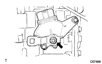
| 1. REMOVE TRANSMISSION CONTROL SHAFT LEVER |
|
Remove the nut, washer and control lever.
| 2. REMOVE PARK/NEUTRAL POSITION SWITCH ASSEMBLY |
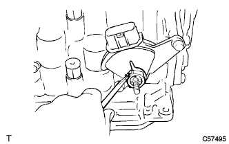 |
Using a screwdriver, release the lock washer.
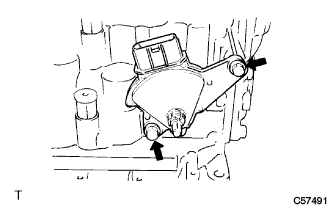 |
Remove the 2 bolts and pull out the park/neutral position switch.
| 3. REMOVE TRANSMISSION REVOLUTION SENSOR |
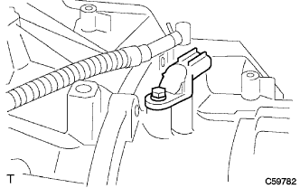 |
Remove the bolt and remove the transmission revolution sensor.
Remove the O-ring from the transmission revolution sensor.
| 4. REMOVE BREATHER PLUG HOSE |
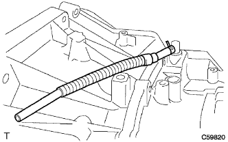 |
Remove the clip and the breather plug hose.
| 5. REMOVE OIL COOLER TUBE UNION |
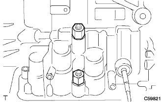 |
Remove the 2 unions.
Remove the 2 O-rings from the unions.
| 6. FIX AUTOMATIC TRANSAXLE ASSEMBLY |
Place the transaxle on wooden blocks.
| 7. REMOVE AUTOMATIC TRANSAXLE OIL PAN SUB-ASSEMBLY |
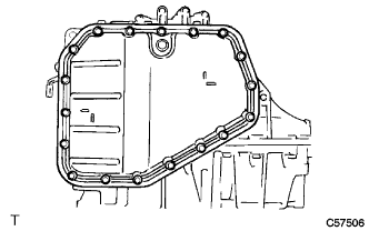 |
Remove the 18 bolts.
Remove the oil pan and the gasket.
Remove the drain plug and the gasket from the oil pan.
| 8. REMOVE VALVE BODY OIL STRAINER ASSEMBLY |
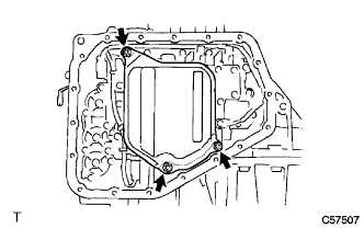 |
Remove the 3 bolts and the oil strainer.
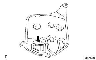 |
Remove the gasket from the oil strainer.
| 9. REMOVE TRANSMISSION VALVE BODY ASSEMBLY |
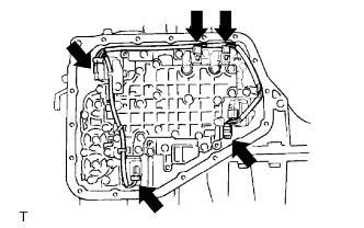 |
Disconnect the ATF temperature sensor from the clamp.
Disconnect the 5 connectors.
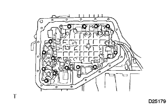 |
Support the valve body assembly and remove the 14 bolts.
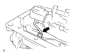 |
Disconnect the manual valve control rod from the manual valve lever, then remove the valve body.
| 10. REMOVE TRANSMISSION WIRE |
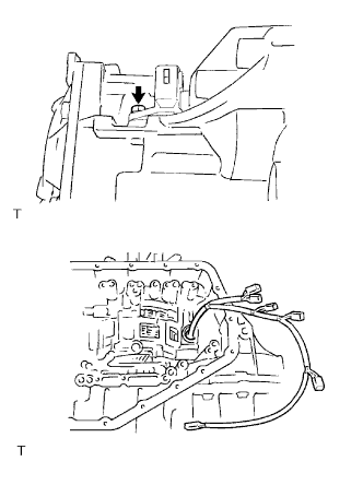 |
Remove the bolt.
Remove the transmission wire from the transaxle case.
Remove the O-ring from the transmission wire.
| 11. REMOVE GOVERNOR APPLY GASKET NO. 1 |
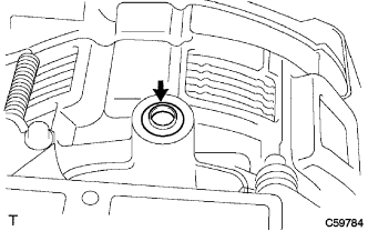 |
Using a screwdriver, remove governor apply gasket No. 1 from the transaxle case.
| 12. REMOVE CHECK BALL BODY |
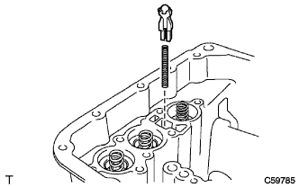 |
Remove the check ball body and the spring.
| 13. REMOVE C-2 ACCUMULATOR PISTON |
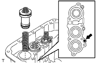 |
Apply compressed air (392 kPa, 4.0 kgf/cm2, 57 psi) to the oil hole and remove the C-2 accumulator piston and spring.
| 14. REMOVE C-2 ACCUMULATOR SPRING SUB-ASSEMBLY |
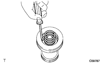 |
Using a screwdriver, remove the snap ring and remove the C-2 accumulator spring.
| 15. REMOVE C-1 ACCUMULATOR PISTON |
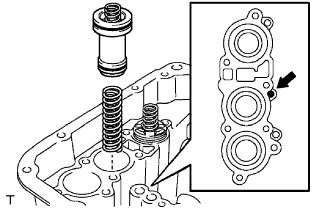 |
Apply compressed air (392 kPa, 4.0 kgf/cm2, 57 psi) to the oil hole and remove the C-1 accumulator piston and spring.
| 16. REMOVE C-1 ACCUMULATOR SPRING SUB-ASSEMBLY |
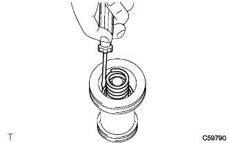 |
Using a screwdriver, remove the C-1 accumulator spring.
| 17. REMOVE PISTON B-1 ACCUMULATOR |
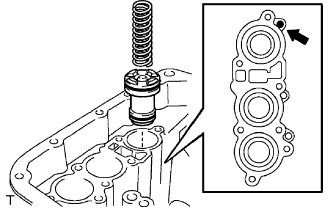 |
Remove B-1 accumulator piston compression spring No. 2.
Apply compressed air (392 kPa, 4.0 kgf/cm2, 57 psi) to the oil hole and remove the B-1 accumulator piston.
| 18. REMOVE B-1 ACCUMULATOR PISTON COMPRESSION SPRING |
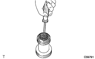 |
Using a screwdriver, remove the B-1 accumulator piston compression spring.
| 19. REMOVE TRANSAXLE HOUSING |
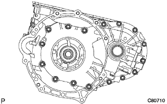 |
Remove the 16 bolts.
Tap around the circumference of the transaxle housing with a plastic hammer to remove the transaxle housing from the transaxle case.
| 20. INSPECT INPUT SHAFT END PLAY |
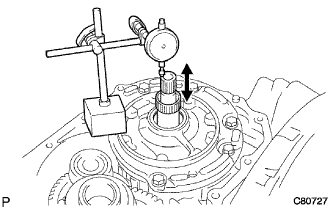 |
Using a dial indicator, measure the input shaft end play.
| 21. REMOVE OIL PUMP ASSEMBLY |
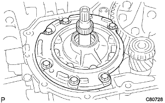 |
Remove the 6 bolts and the oil pump assembly from the transaxle case.
| 22. REMOVE INPUT SHAFT ASSEMBLY |
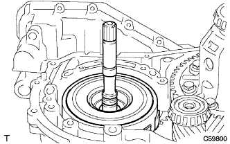 |
Remove the input shaft assembly from the transaxle case.
| 23. REMOVE STATOR SHAFT THRUST NEEDLE ROLLER BEARING |
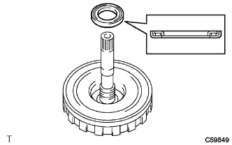 |
Remove the thrust needle roller bearing from the input shaft.
| 24. REMOVE PLANETARY GEAR FRONT THRUST NEEDLE ROLLER BEARING |
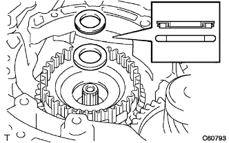 |
Remove the thrust needle roller bearing and the thrust bearing race from the direct clutch hub.
| 25. REMOVE DIRECT CLUTCH HUB |
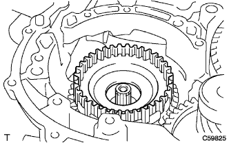 |
Remove the direct clutch hub from the transaxle case.
| 26. REMOVE DIFFERENTIAL GEAR ASSEMBLY |
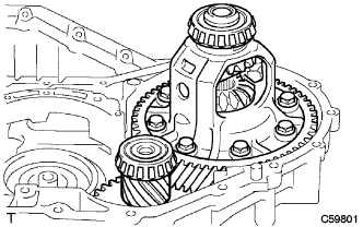 |
Remove the differential gear assembly and differential drive pinion from the transaxle case.
| 27. REMOVE GOVERNOR APPLY GASKET NO. 2 |
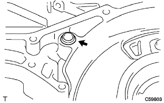 |
Remove governor apply gasket No. 2 from the transaxle case.
| 28. REMOVE TRANSAXLE REAR COVER ASSEMBLY |
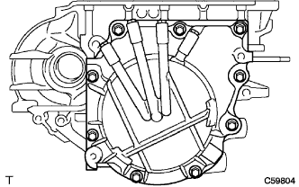 |
Remove the 9 bolts.
Tap around the circumference of the transaxle rear cover with a plastic hammer to remove the transaxle rear cover from the transaxle case.
| 29. REMOVE TRANSAXLE CASE 2ND BRAKE GASKET |
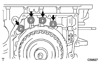 |
Using a screwdriver, remove the 4 transaxle case 2nd brake gaskets.
| 30. REMOVE FRONT CLUTCH DRUM THRUST NEEDLE ROLLER BEARING |
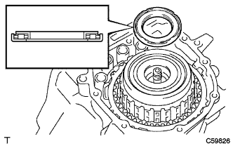 |
Using a magnetic finger, remove the clutch drum thrust needle roller bearing.
| 31. REMOVE INTERMEDIATE SHAFT ASSEMBLY |
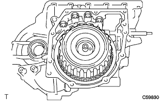 |
Remove the intermediate shaft assembly from the transaxle case.
| 32. REMOVE SUN GEAR REAR THRUST BEARING |
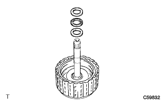 |
Remove the thrust sun gear rear thrust bearing and the 2 thrust bearing races from the intermediate shaft.
| 33. REMOVE 2ND COAST AND OVERDRIVE BRAKE DISC |
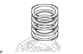 |
Remove the flange, 2 discs and 2 plates from the transaxle case.
| 34. REMOVE 2ND COAST AND OVERDRIVE BRAKE FLANGE HOLE SNAP RING |
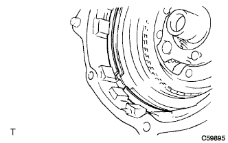 |
Using a screwdriver, remove the 2nd coast and the over drive hole snap ring from the transaxle case.
| 35. REMOVE FORWARD CLUTCH HUB SUB-ASSEMBLY |
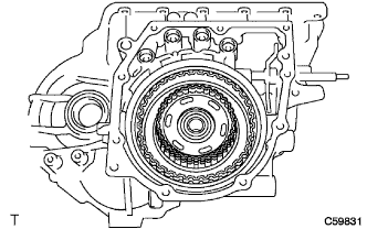 |
Remove the forward clutch hub sub-assembly from the transaxle case.
| 36. REMOVE FORWARD CLUTCH HUB THRUST NEEDLE ROLLER BEARING |
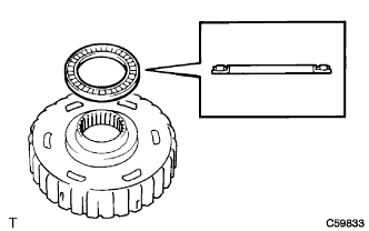 |
Remove the forward clutch hub thrust needle roller bearing from the forward clutch hub.
| 37. REMOVE FORWARD CLUTCH HUB THRUST BEARING RACE |
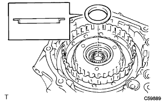 |
Remove the forward clutch hub thrust bearing race from the planetary sun gear.
| 38. REMOVE REAR PLANETARY SUN GEAR ASSEMBLY |
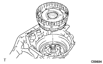 |
Remove the rear planetary sun gear assembly from the transaxle case.
| 39. REMOVE PLANETARY GEAR REAR THRUST NEEDLE ROLLER BEARING |
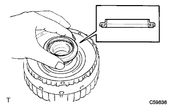 |
Remove the planetary gear rear thrust needle roller bearing from the rear planetary sun gear.
| 40. INSPECT 1 WAY CLUTCH ASSEMBLY |
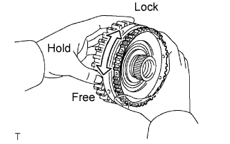 |
Hold the rear planetary sun gear and turn the 1-way clutch.
Make sure that the 1-way clutch turns freely clockwise and locks when turned counterclockwise.
| 41. REMOVE 1 WAY CLUTCH ASSEMBLY |
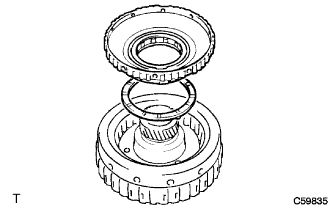 |
Remove the 1 way clutch assembly and planetary carrier thrust washer No. 2 from the rear planetary sun gear.
| 42. REMOVE PLANETARY CARRIER THRUST WASHER |
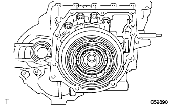 |
Remove the planetary carrier thrust washer from the transaxle case.
| 43. REMOVE PLANETARY SUN GEAR SUB-ASSEMBLY |
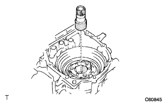 |
Remove the planetary sun gear sub-assembly from the transaxle case.
| 44. REMOVE FRONT PLANETARY FLANGE FRONT THRUST BEARING RACE |
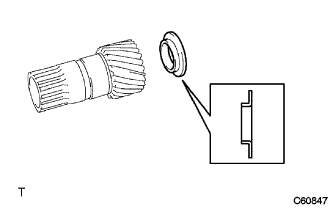 |
Remove the front planetary flange front thrust bearing race from the planetary sun gear.
| 45. REMOVE SECOND BRAKE PISTON ASSEMBLY |
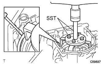 |
Using SST, a press and a screwdriver, remove the snap ring.
Remove the second brake piston assembly from the transaxle case.
| 46. REMOVE 2ND BRAKE PISTON RETURN SPRING SUB-ASSEMBLY |
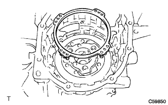 |
Remove the 2nd brake piston return spring sub-assembly from the transaxle case.
| 47. REMOVE 2ND BRAKE BRAKE DISC |
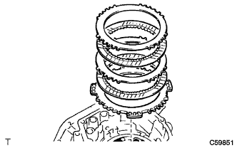 |
Remove the 2 plates, 2 discs and flange from the transaxle case.
| 48. REMOVE BRAKE DRUM GASKET |
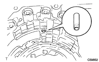 |
Remove the brake drum gasket from the transaxle case.
| 49. REMOVE OUTER RACE RETAINER |
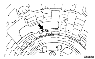 |
Remove the outer race retainer from the transaxle case.
| 50. INSPECT 1 WAY CLUTCH NO. 2 |
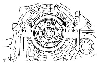 |
Check that the planetary gear turns freely counterclockwise and locks when turned clockwise.
| 51. REMOVE 1-WAY CLUTCH NO. 2 |
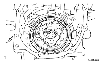 |
Remove 1-way clutch No. 2 from the transaxle case.
| 52. REMOVE PLANETARY GEAR ASSEMBLY |
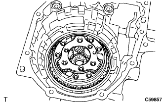 |
Remove the planetary gear assembly from the transaxle case.
| 53. REMOVE 1ST AND REVERSE BRAKE DISC |
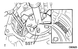 |
Using SST, a press and a screwdriver, remove the snap ring.
Remove the flange, 4 discs and 4 plates from the transaxle case.
| 54. REMOVE 1ST AND REVERSE BRAKE RETURN SPRING SUB-ASSEMBLY |
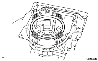 |
Remove the 1st and reverse brake return spring sub-assembly from the transaxle case.
| 55. REMOVE COUNTER DRIVE GEAR NUT |
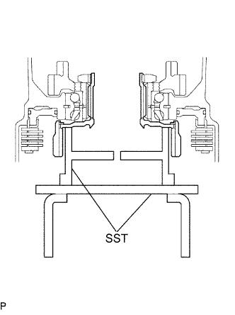 |
Using SST, lift the transaxle case.
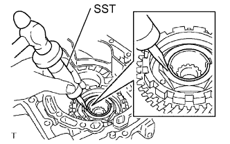 |
Using SST and a hammer, release the counter drive gear nut.
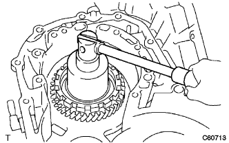 |
Using a 55 mm socket wrench, remove the counter drive gear nut from the planetary ring gear flange.
| 56. REMOVE PLANETARY RING GEAR FLANGE |
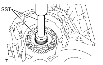 |
Using SST and a press, remove the planetary ring gear.
| 57. REMOVE PLANETARY RING GEAR |
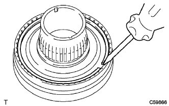 |
Using a screwdriver, remove the snap ring.
Remove the planetary ring gear from the planetary ring gear flange.
| 58. REMOVE COUNTER DRIVE GEAR |
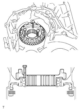 |
Install the counter drive gear with the 3 bolts.
Rotate the 3 bolts and remove the counter drive gear and planetary ring gear.
| 59. REMOVE 1ST AND REVERSE BRAKE PISTON |
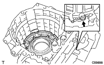 |
Apply compressed air (392 kPa, 4.0 kgf/cm2, 57 psi) to the transaxle case to remove the 1st and reverse brake piston.
| 60. REMOVE 1ST AND REVERSE BRAKE O-RING |
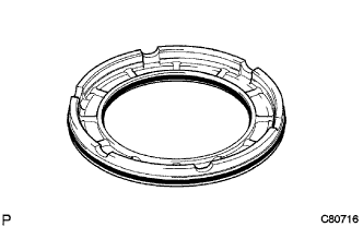 |
Remove the 2 1st and reverse brake O-rings from the 1st and reverse brake piston.
| 61. REMOVE PARKING LOCK PAWL BRACKET |
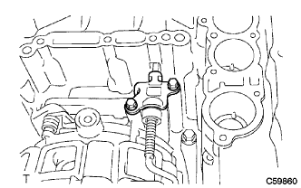 |
Remove the 2 bolts and the parking lock pawl bracket.
| 62. REMOVE MANUAL VALVE LEVER SHAFT |
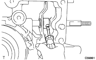 |
Using a screwdriver, cut off the manual valve lever shaft spacer to remove the manual valve lever shaft.
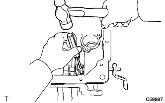 |
Using a pin punch and hammer, drive out the pin.
Remove the manual valve lever shaft and manual valve lever.
| 63. REMOVE PARKING LOCK ROD SUB-ASSEMBLY |
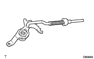 |
Remove the parking lock rod sub-assembly from the manual valve lever.
| 64. REMOVE MANUAL DETENT SPRING SUB-ASSEMBLY |
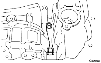 |
Remove the bolt and the manual detent spring sub-assembly.
| 65. REMOVE PARKING LOCK PAWL |
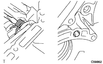 |
Remove the parking lock pawl shaft, torsion spring and parking lock pawl.
| 66. REMOVE TRANSAXLE CASE NO. 1 PLUG |
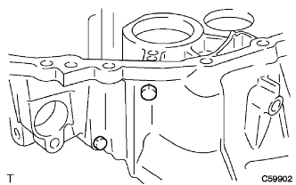 |
Remove the 2 transaxle case No. 1 plugs from the transaxle housing.
Using a screwdriver, remove the 2 O-rings from the 2 transaxle case No. 1 plugs.
| 67. REMOVE TRANSAXLE HOUSING NO. 2 PLUG |
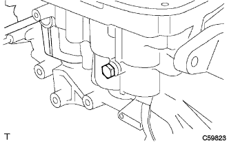 |
Remove the transaxle housing No. 2 plug from the transaxle case.
Using a screwdriver, remove the O-ring from the transaxle housing No. 2 plug.
| 68. REMOVE MANUAL VALVE LEVER SHAFT OIL SEAL |
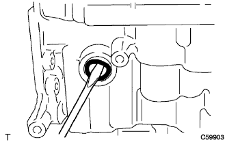 |
Using a screwdriver, remove the oil seal from the transaxle case.
| 69. REMOVE TRANSAXLE HOUSING OIL SEAL |
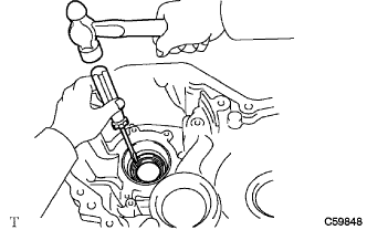 |
Using a screwdriver and a hammer, remove the transaxle housing oil seal.
| 70. REMOVE TRANSAXLE CASE OIL SEAL |
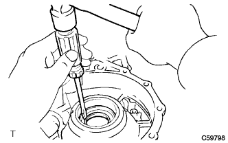 |
Using a screwdriver and hammer, remove the transaxle case oil seal.
| 71. REMOVE TRANSMISSION CASE PLATE NO. 1 |
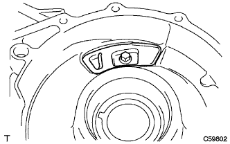 |
Remove the bolt and transmission case plate No. 1 from the transaxle case.
| 72. REMOVE TRANSAXLE HOUSING OIL SEPARATOR |
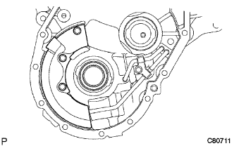 |
Remove the 3 bolts and the oil separator from the transaxle housing.
| 73. REMOVE TRANSAXLE APPLY TUBE CLAMP NO. 1 |
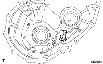 |
Remove the bolt and transaxle apply tube clamp No. 1 from the transaxle housing.
| 74. REMOVE TRANSMISSION LUBE APPLY TUBE |
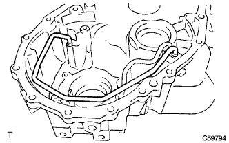 |
Remove the transmission lube apply tube from the transaxle housing.
| 75. REMOVE DIFFERENTIAL GEAR LUBE APPLY TUBE |
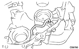 |
Remove the differential gear lube apply tube from the transaxle housing.
| 76. REMOVE BREATHER PLUG NO. 1 |
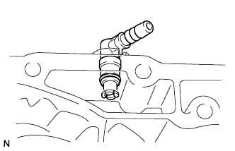 |
Remove breather plug No. 1 from the transaxle case.
Using a screwdriver, remove the O-ring from breather plug No. 1.