BRAKE BOOSTER (for Hatchback LHD) > REMOVAL |
| 1. DISCONNECT CABLE FROM NEGATIVE BATTERY TERMINAL |
| 2. DRAIN BRAKE FLUID |
| 3. REMOVE FRONT WIPER ARM HEAD CAP |
|
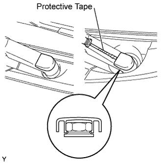
Using a screwdriver with its tip wrapped in protective tape, disengage the claw and remove the 2 front wiper arm head caps.
| 4. REMOVE FRONT WIPER ARM AND BLADE ASSEMBLY LH |
Operate the wiper, then stop the windshield wiper motor in the automatic stop position.
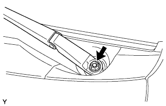 |
Remove the nut and front wiper arm.
| 5. REMOVE FRONT WIPER ARM AND BLADE ASSEMBLY RH |
| 6. REMOVE HOOD TO COWL TOP SEAL |
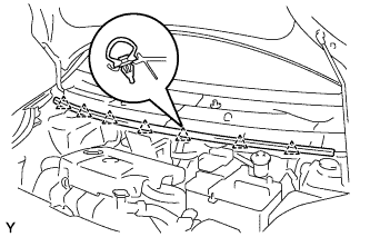 |
Disengage the 7 clips and remove the hood to cowl top seal.
| 7. REMOVE COWL TOP VENTILATOR LOUVER SUB-ASSEMBLY |
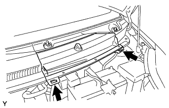 |
Disengage the 2 hooks and remove cowl top ventilator louver center No. 1.
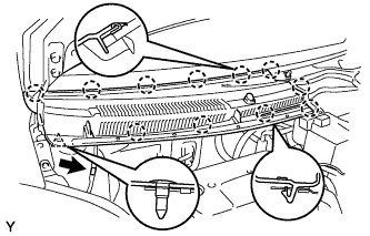 |
Disconnect the washer hose.
Disengage the 11 claws and clip.
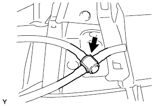 |
Disconnect the washer hose and remove the cowl top ventilator louver sub-assembly.
| 8. REMOVE COWL TOP VENTILATOR LOUVER LH |
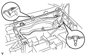 |
Remove the 2 clips.
Disengage the 4 claws and remove the cowl top ventilator louver LH.
| 9. REMOVE FRONT WIPER MOTOR AND LINK |
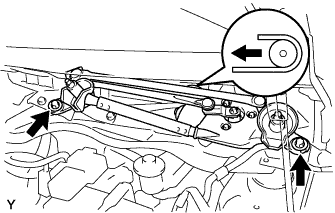 |
Remove the 2 bolts.
Slide the wiper link. Disengage the meshing of the rubber pin, then disconnect the connector and remove the front wiper motor and link.
| 10. REMOVE NO. 2 COWL TO REGISTER DUCT SUB-ASSEMBLY |
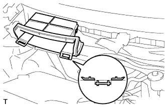 |
Disengage the claw and remove cowl to register duct sub-assembly No. 2.
| 11. REMOVE COWL TOP PANEL OUTER |
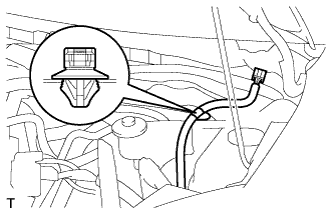 |
Disengage the wire harness clamp.
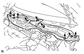 |
Remove the 9 bolts and remove the cowl top panel outer.
| 12. REMOVE INSTRUMENT PANEL NO. 1 UNDER COVER SUB-ASSEMBLY (w/ Instrument Panel No. 1 Under Cover Sub-assembly) |
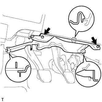 |
Remove the 2 screws.
Disengage the 3 claws and remove the instrument panel under cover.
| 13. REMOVE INSTRUMENT PANEL UNDER TRAY (w/o Driver Side Knee Airbag) |
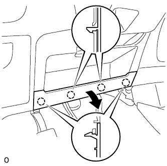 |
Disengage the 4 claws and open the instrument panel under tray.
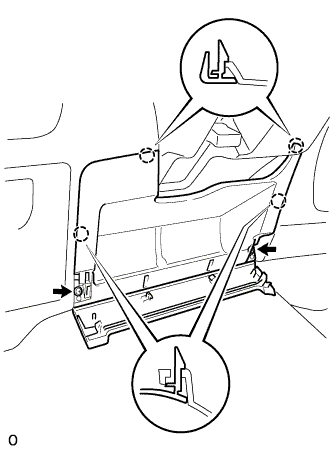 |
Remove the 2 <A> screws.
Disengage the 4 claws and remove the instrument panel under tray.
| 14. REMOVE STEERING COLUMN COVER (w/ Driver Side Knee Airbag) |
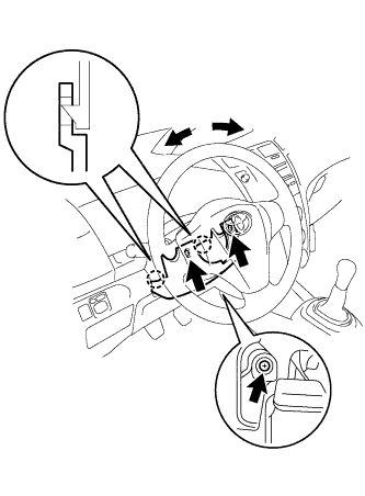 |
Turn the steering wheel 90 degrees in both directions and remove the 2 screws.
Remove the screw from the lower portion of the steering cover lower.
Disengage the 2 claws and remove the steering column cover lower.
| 15. REMOVE DRIVER SIDE KNEE AIRBAG ASSEMBLY (w/ Driver Side Knee Airbag) |
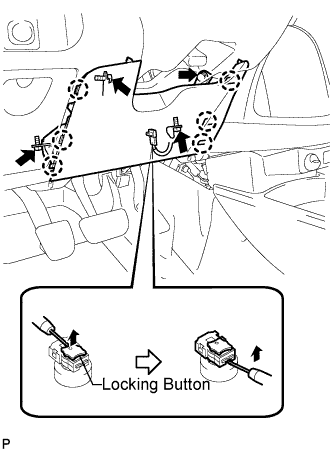 |
Remove the 4 bolts.
Disengage the 6 claws and remove the driver side knee airbag assembly.
Using a thin-bladed screwdriver, release the locking button.
Using a thin-bladed screwdriver, disconnect the airbag connector and remove the instrument panel wire.
| 16. REMOVE BATTERY |
| 17. REMOVE BATTERY TRAY |
| 18. REMOVE BATTERY CARRIER |
| 19. REMOVE BRAKE ACTUATOR (w/ ABS) |
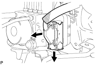 |
Release the lock lever and disconnect the brake actuator connector.
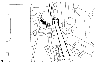 |
Using a union nut wrench (10 mm), separate the brake tube from the front flexible hose.
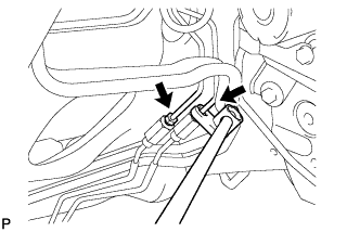 |
Using a union nut wrench (10 mm), separate the 2 brake tubes from the brake tube No. 1 way.
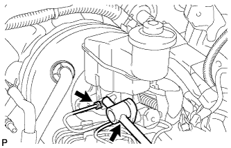 |
Using a union nut wrench (10 mm), separate the 2 brake tubes from the brake master cylinder.
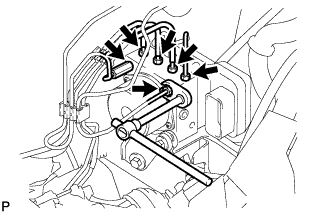 |
Using a union nut wrench (10 mm), separate the 6 brake tubes from the brake actuator.
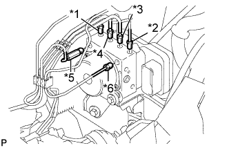 |
Use tags or labels to identify the place to reconnect each brake tube.
| *1 | To Front Wheel RH |
| *2 | To Front Wheel LH |
| *3 | To Rear Wheel RH |
| *4 | To Rear Wheel LH |
| *5 | From Master Cylinder |
| *6 | From Master Cylinder |
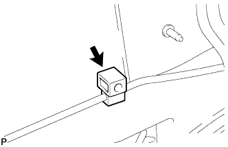 |
Disconnect the brake tube clamp.
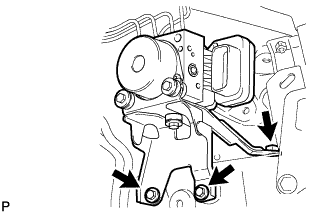 |
Remove the 3 bolts and the actuator with bracket.
| 20. DISCONNECT CLUTCH RESERVOIR TUBE (for Manual Transaxle) |
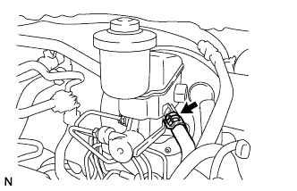 |
Slide the clip and disconnect the reservoir tube.
| 21. REMOVE BRAKE MASTER CYLINDER SUB-ASSEMBLY |
Disconnect the brake fluid level warning switch connector.
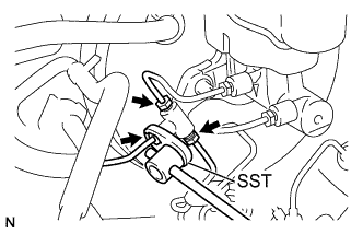 |
w/o ABS:
Using SST, separate the 3 brake tubes from the brake tube way.
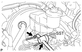 |
Using SST, separate the 2 brake tubes from the brake master cylinder sub-assembly.
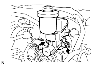 |
w/ ABS:
Remove the 2 nuts and remove the brake master cylinder sub-assembly.
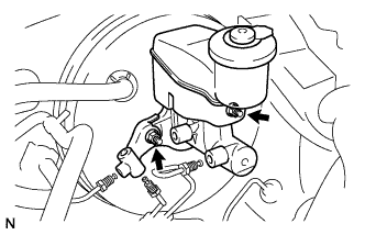 |
w/o ABS:
Remove the 2 nuts and brake tube way and remove the brake master cylinder sub-assembly.
Remove the O-ring from the brake master cylinder sub-assembly.
| 22. SEPARATE BRAKE MASTER CYLINDER PUSH ROD CLEVIS |
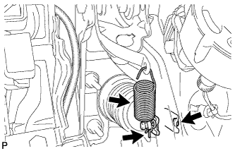 |
Remove the brake pedal return spring.
Remove the clip and the push rod pin and separate the push rod clevis from the brake pedal.
| 23. REMOVE BRAKE BOOSTER |
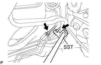 |
w/o ABS:
Using SST, separate the 2 brake tubes from the brake tube No. 1 way.
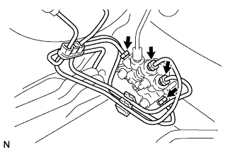 |
Using SST, remove the brake tube assembly from the proportioning valve.
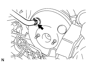 |
Slide the clip and disconnect the vacuum hose from the check valve.
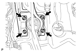 |
Remove the 4 nuts and remove the brake booster.
Remove the gasket from the brake booster.
Loosen the push rod lock nut and remove the push rod clevis.
| 24. REMOVE BRAKE VACUUM CHECK VALVE ASSEMBLY |
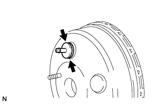 |
Remove the vacuum check valve from the brake booster.
Remove the grommet from the brake booster.