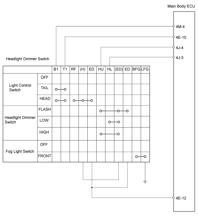
LIGHTING SYSTEM > Light Control Switch Circuit |
| 1.CHECK HARNESS AND CONNECTOR (MAIN BODY ECU - HEADLIGHT DIMMER SWITCH) |
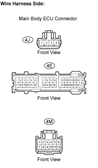 |
Disconnect the 4M, 4E and 4J main body ECU connectors.
Measure the resistance.
| Tester connection | Condition | Specified condition |
| 4M-4 - 4E-12 | Light control switch OFF → HEAD | 10 kΩ or higher → Below 1 Ω |
| 4E-10 - 4E-12 | Light control switch OFF → HEAD | 10 kΩ or higher → Below 1 Ω |
| 4J-4 - 4E-12 | Light control switch OFF → HEAD Headlight dimmer switch LOW → HIGH | 10 kΩ or higher → Below 1 Ω |
| 4J-4 - 4E-12 | Light control switch OFF → HEAD Headlight dimmer switch LOW → FLASH | 10 kΩ or higher → Below 1 Ω |
| 4J-3 - 4E-12 | Light control switch OFF → HEAD Headlight dimmer switch LOW | 10 kΩ or higher → Below 1 Ω |
Reconnect the main body ECU connectors.
|
| ||||
| OK | ||
 | ||
| ||
| 2.INSPECT HEADLIGHT DIMMER SWITCH |
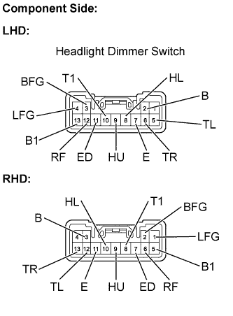 |
Inspect the light control switch.
Measure the resistance.
| Tester connection | Condition | Specified condition |
| 10 (T1) - 13 (B1) 11 (ED) - 12 (RF) | OFF | 10 kΩ or higher |
| 10 (T1) - 13 (B1) | TAIL, HEAD | Below 1 Ω |
| 11 (ED) - 12 (RF) | HEAD | Below 1 Ω |
| Tester connection | Condition | Specified condition |
| 5 (B1) - 8 (T1) 6 (RF) - 7 (ED) | OFF | 10 kΩ or higher |
| 5 (B1) - 8 (T1) | TAIL, HEAD | Below 1 Ω |
| 6 (RF) - 7 (ED) | HEAD | Below 1 Ω |
Inspect the headlight dimmer switch.
Measure the resistance.
| Tester connection | Condition | Specified condition |
| 9 (HU) - 11 (ED) | FLASH | Below 1 Ω |
| 8 (HL) - 11 (ED) | LOW BEAM | Below 1 Ω |
| 9 (HU) - 11 (ED) | HI BEAM | Below 1 Ω |
| Tester connection | Condition | Specified condition |
| 9 (HU) - 7 (ED) | FLASH | Below 1 Ω |
| 10 (HL) - 7 (ED) | LOW BEAM | Below 1 Ω |
| 9 (HU) - 7 (ED) | HI BEAM | Below 1 Ω |
Inspect the turn signal switch.
Measure the resistance.
| Tester connection | Condition | Specified condition |
| 5 (TL) - 7 (E) 6 (TR) - 7 (E) | OFF | 10 kΩ or higher |
| 5 (TL) - 7 (E) | Left | Below 1 Ω |
| 6 (TR) - 7 (E) | Right | Below 1 Ω |
| Tester connection | Condition | Specified condition |
| 11 (E) - 12 (TL) 11 (E) - 13 (TR) | OFF | 10 kΩ or higher |
| 11 (E) - 12 (TL) | Right | Below 1 Ω |
| 11 (E) - 13 (TR) | Left | Below 1 Ω |
Inspect the fog light switch.
Measure the resistance.
| Tester connection | Condition | Specified condition |
| 3 (BFG) - 4 (LFG) | OFF | 10 kΩ or higher |
| 3 (BFG) - 4 (LFG) | Fog light switch ON | Below 1 Ω |
| Tester connection | Condition | Specified condition |
| 1 (LFG) - 2 (BFG) | OFF | 10 kΩ or higher |
| 1 (LFG) - 2 (BFG) | Fog light switch ON | Below 1 Ω |
|
| ||||
| OK | ||
| ||
| ||

