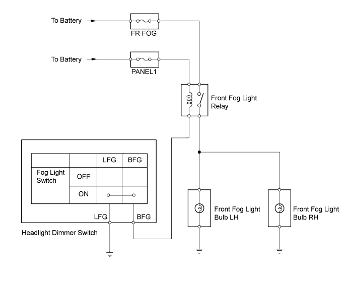
LIGHTING SYSTEM > Front Fog Light Circuit |
| 1.INSPECT WHETHER FRONT FOG LIGHTS ILLUMINATE |
Check whether the front fog lights illuminate.
| Condition | Proceed to |
| Neither left nor right fog light illuminates | A |
| Either left or right fog light illuminates | B |
|
| ||||
| A | |
 |
| 2.INSPECT FUSE (FR FOG, PANEL1) |
Remove the FR FOG and PANEL1 fuses from the main body ECU.
Measure the resistance.
Reinstall the FR FOG and PANEL1 fuses.
|
| ||||
| OK | |
|
| 3.INSPECT FRONT FOG LIGHT RELAY |
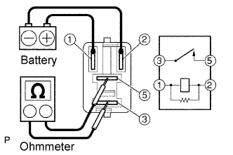 |
Remove the front fog light relay.
Measure the resistance.
| Tester Connection | Specified Condition |
| 3 - 5 | 10 kΩ or higher |
| 3 - 5 | Below 1 Ω (Apply battery voltage to terminals 2 and 1) |
Reinstall the front fog light relay.
|
| ||||
| OK | |
|
| 4.CHECK HARNESS AND CONNECTOR (BATTERY - FRONT FOG LIGHT RELAY) |
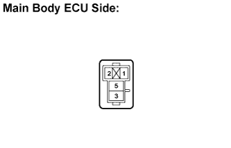 |
Remove the front fog light relay.
Measure the voltage.
| Tester Connection | Condition | Specified Condition |
| 2 - Body ground | Light control switch TAIL | 10 to 14 V |
| 5 - Body ground | Always | 10 to 14 V |
Reinstall the front fog light relay.
|
| ||||
| OK | |
|
| 5.INSPECT HEADLIGHT DIMMER SWITCH |
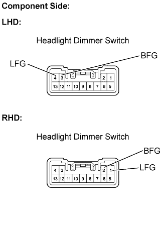 |
Remove the headlight dimmer switch.
Inspect the fog light switch.
Measure the resistance.
| Tester Connection | Condition | Specified Condition |
| 3 (BFG) - 4 (LFG) | Fog light switch OFF | 10 kΩ or higher |
| 3 (BFG) - 4 (LFG) | Fog light switch ON | Below 1 Ω |
| Tester Connection | Condition | Specified Condition |
| 1 (LFG) - 2 (BFG) | Fog light switch OFF | 10 kΩ or higher |
| 1 (LFG) - 2 (BFG) | Fog light switch ON | Below 1 Ω |
Reinstall the headlight dimmer switch.
|
| ||||
| OK | |
|
| 6.CHECK HARNESS AND CONNECTOR (FRONT FOG LIGHT RELAY - HEADLIGHT DIMMER SWITCH) |
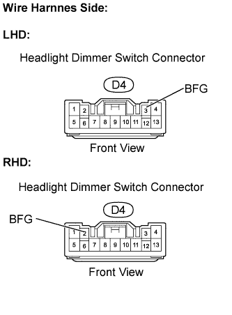 |
Disconnect the D4 headlight dimmer switch connector.
Measure the voltage.
| Tester Connection | Condition | Specified Condition |
| D4-3 (BFG) - Body ground | Always | 10 to 14 V |
| Tester Connection | Condition | Specified Condition |
| D4-2 (BFG) - Body ground | Always | 10 to 14 V |
Reconnect the headlight dimmer switch connector.
|
| ||||
| OK | ||
 | ||
| ||
| 7.INSPECT BULB (FRONT FOG LIGHT BULB) |
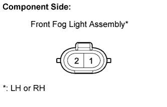 |
Remove the front fog light assembly.
Apply battery voltage to the terminals and check that the front fog light illuminates.
| Measurement Condition | Standard |
| Positive battery - Terminal 2 Negative battery - Terminal 1 | Front fog light illuminates |
Reinstall the front fog light assembly.
|
| ||||
| OK | |
|
| 8.CHECK HARNESS AND CONNECTOR (FRONT FOG LIGHT RELAY - FRONT FOG LIGHT ASSEMBLY) |
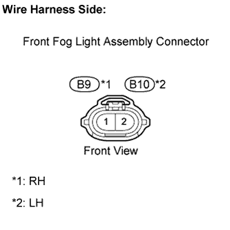 |
Disconnect the B9 and B10 front fog light assembly connectors.
Measure the voltage.
| Tester Connection | Switch Condition | Specified Condition |
| B9-2 - Body ground | Ignition switch ON Light control switch TAIL Fog light switch ON | 10 to 14 V |
| B10-2 - Body ground | Ignition switch ON Light control switch TAIL Fog light switch ON | 10 to 14 V |
Reconnect the front fog light assembly connectors.
|
| ||||
| OK | ||
| ||
| ||

