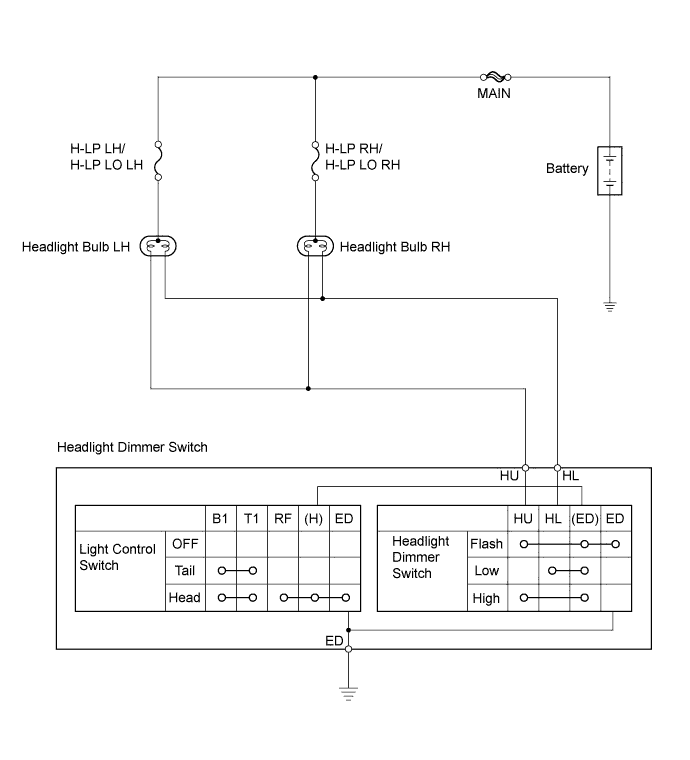
LIGHTING SYSTEM > Headlight Signal Circuit |
| 1.INSPECT FUSE (H-LP RH/H-LP LO RH, H-LP LH/H-LP LO LH) |
Remove the H-LP RH/H-LP LO RH and H-LP LH/H-LP LO LH fuses from the engine room relay block.
Measure the resistance.
Reinstall the H-LP RH/H-LP LO RH and H-LP LH/H-LP LO LH fuses.
|
| ||||
| OK | |
 |
| 2.INSPECT BULB (HEADLIGHT BULB) |
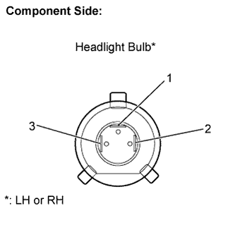 |
Disconnect the B4 and B6 headlight connectors.
Apply battery voltage to the terminals and check that the headlight illuminates.
| Measurement Condition | Standard |
| Positive battery - Terminal 1 Negative battery - Terminal 3 | Headlight illuminates (HI-Beam) |
| Positive battery - Terminal 2 Negative battery - Terminal 3 | Headlight illuminates (LO-Beam) |
Reconnect the headlight connectors.
|
| ||||
| OK | |
|
| 3.CHECK HARNESS AND CONNECTOR (FUSE - HEADLIGHT) |
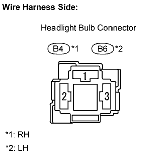 |
Disconnect the B4 and B6 headlight bulb connectors.
Measure the voltage.
| Tester Connection | Condition | Specified Condition |
| B4-3 - Body ground | Always | 10 to 14 V |
| B6-3 - Body ground | Always | 10 to 14 V |
Reconnect the headlight bulb connectors.
|
| ||||
| OK | |
|
| 4.INSPECT HEADLIGHT DIMMER SWITCH |
Remove the headlight dimmer switch.
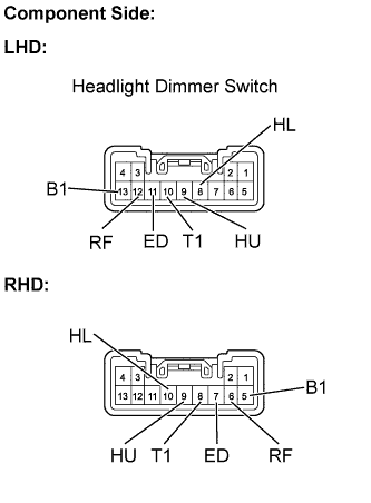 |
Inspect light control switch.
Measure the resistance.
| Tester Connection | Condition | Specified Condition |
| 10 (T1) - 13 (B1) | TAIL | Below 1 Ω |
| 10 (T1) - 13 (B1) | HEAD | Below 1 Ω |
| 11 (ED) - 12 (RF) | HEAD | Below 1 Ω |
| Tester Connection | Condition | Specified Condition |
| 5 (B1) - 8 (T1) | TAIL | Below 1 Ω |
| 5 (B1) - 8 (T1) | HEAD | Below 1 Ω |
| 6 (RF) - 7 (ED) | HEAD | Below 1 Ω |
Inspect headlight dimmer switch.
Measure the resistance.
| Tester Connection | Condition | Specified Condition |
| 9 (HU) - 11 (ED) | FLASH | Below 1 Ω |
| 8 (HL) - 11 (ED) | LOW BEAM | Below 1 Ω |
| 9 (HU) - 11 (ED) | HI BEAM | Below 1 Ω |
| Tester Connection | Condition | Specified Condition |
| 7 (ED)- 9 (HU) | FLASH | Below 1 Ω |
| 7 (ED) - 10 (HL) | LOW BEAM | Below 1 Ω |
| 7 (ED) - 9 (HU) | HI BEAM | Below 1 Ω |
Reinstall the headlight dimmer switch.
|
| ||||
| OK | |
|
| 5.CHECK HARNESS AND CONNECTOR (HEADLIGHT - HEADLIGHT DIMMER SWITCH) |
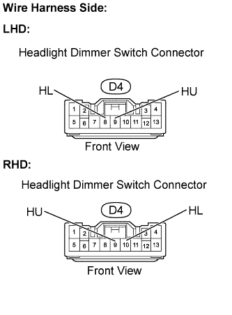 |
Disconnect the D4 headlight dimmer switch connector.
Measure the voltage.
| Tester Connection | Condition | Specified Condition |
| D4-8 (HL) - Body ground | Always | 10 to 14 V |
| D4-9 (HU) - Body ground | Always | 10 to 14 V |
| Tester Connection | Condition | Specified Condition |
| D4-9 (HU) - Body ground | Always | 10 to 14 V |
| D4-10 (HL) - Body ground | Always | 10 to 14 V |
Reconnect the headlight dimmer switch connector.
|
| ||||
| OK | ||
 | ||
| ||
