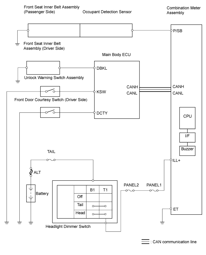
METER / GAUGE SYSTEM (for Hatchback) > Warning Buzzer does not Sound |
| 1.CHECK BUZZER (SEAT BELT, KEY REMINDER, TAIL LIGHT REMINDER) |
Check that the seat belt warning, key reminder and taillight reminder warning buzzers sound.
| Result | Proceed to |
| Seat belt warning buzzer does not sound (where equipped with seat belt warning system) | A |
| Key reminder warning buzzer does not sound (where equipped with key reminder warning system) | B |
| Taillight reminder warning buzzer does not sound (Meter illuminations normal) | C |
| No warning buzzers sound | D |
|
| ||||
|
| ||||
|
| ||||
| A | |
 |
| 2.CHECK SEAT BELT WARNING BUZZER |
Check which seat belt warning buzzer (driver or front passenger) does not sound.
| Result | Proceed to |
| Driver side | A |
| Passenger side | B |
|
| ||||
| A | |
|
| 3.READ VALUE USING INTELLIGENT TESTER (D-SEAT BUCKLE SW) |
Connect the intelligent tester to the DLC3.
Turn the ignition switch ON and turn the tester on.
Read the Data List according to the prompts displayed on the tester
| Item | Measurement Item/Range (Display) | Normal Condition | Diagnostic Note |
| D Seat Buckle SW | Buckle switch (Driver side) / UNSET: Driver seat belt is not fastened SET: Driver seat belt is fastened NG: Data is not determined | UNSET / SET | - |
|
| ||||
| NG | |
|
| 4.CHECK FRONT SEAT INNER BELT ASSEMBLY (DRIVER SIDE) |
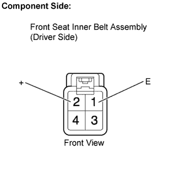 |
LHD:
Disconnect the J35 front seat inner belt assembly (driver side) connector.
Measure the resistance.
| Tester connection | Condition | Specified Condition |
| 1 (E) - 2 (+) | Tongue plate fastened | Below 1Ω |
| 1 (E) - 2 (+) | Tongue plate released | 10 kΩ or higher |
Reconnect the front seat inner belt assembly (driver side) connector.
RHD:
Disconnect the J34 front seat inner belt assembly (driver side) connector.
Measure the resistance.
| Tester connection | Condition | Specified Condition |
| 1 (E) - 2 (+) | Tongue plate fastened | Below 1Ω |
| 1 (E) - 2 (+) | Tongue plate released | 10 kΩ or higher |
Reconnect the front seat inner belt assembly (driver side) connector.
|
| ||||
| OK | |
|
| 5.CHECK HARNESS AND CONNECTOR (FRONT SEAT INNER BELT ASSEMBLY (DRIVER SIDE) - MAIN BODY ECU) |
LHD:
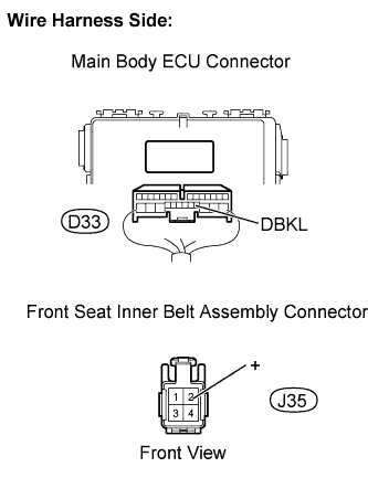 |
Disconnect the J35 front seat inner belt assembly (driver side) connector.
Disconnect the D33 main body ECU connector.
Measure the resistance.
| Tester Connection | Condition | Specified Condition |
| D33-9 (DBKL) - J35-2 (+) | Tongue plate fastened | Below 1Ω |
| D33-9 (DBKL) - J35-2 (+) | Tongue plate released | 10 kΩ or higher |
Reconnect the front seat inner belt assembly (driver side) connector.
Reconnect the main body ECU.
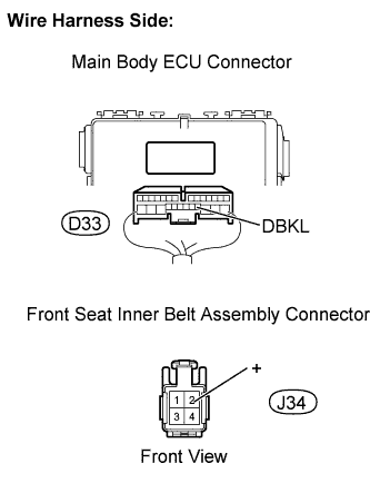 |
RHD:
Disconnect the J34 front seat inner belt assembly (driver side) connector.
Disconnect the D33 main body ECU connector.
Measure the resistance.
| Tester Connection | Condition | Specified Condition |
| D33-9 (DBKL) - J34-2 (+) | Tongue plate fastened | Below 1Ω |
| D33-9 (DBKL) - J34-2 (+) | Tongue plate released | 10 kΩ or higher |
Reconnect the front seat inner belt assembly (driver side) connector.
Reconnect the main body ECU.
|
| ||||
| OK | ||
 | ||
| ||
| 6.READ VALUE USING INTELLIGENT TESTER (P-SEAT BELT BUCKLE SW) |
Connect the intelligent tester to the DLC3.
Turn the ignition switch ON and turn the tester on.
Read the Data List according to the prompts displayed on the tester
| Item | Measurement Item/Range (Display) | Normal Condition | Diagnostic Note |
| P-Seat belt Buckle SW | Buckle switch (Passenger side) / UNSET: Front passenger seat belt is not fastened SET: Front passenger seat belt is fastened NG: Data is not determined | UNSET / SET | - |
|
| ||||
| NG | |
|
| 7.CHECK FRONT SEAT INNER BELT ASSEMBLY (PASSENGER SIDE) |
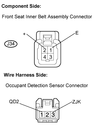 |
LHD:
Disconnect the J34 front seat inner belt assembly (passenger side) connector.
Disconnect the occupant detection sensor connector.
Measure the resistance.
| Tester Connection | Condition | Specified Condition |
| 1 (E) - 1 (QD2) | Tongue plate fastened | 10 kΩ or higher |
| 1 (E) - 1 (QD2) | Tongue plate unfastened | Below 1Ω |
| 2 (+) - 3 (ZJK) | Always | Below 1Ω |
Reconnect the front seat inner belt assembly (passenger side) connector.
Reconnect the occupant detection sensor connector.
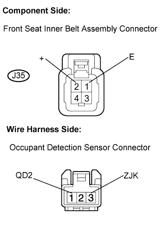 |
RHD:
Disconnect the J35 front seat inner belt assembly (passenger side) connector.
Disconnect the occupant detection sensor connector.
Measure the resistance.
| Tester Connection | Condition | Specified Condition |
| 1 (E) - 1 (QD2) | Tongue plate fastened | 10 kΩ or higher |
| 1 (E) - 1 (QD2) | Tongue plate unfastened | Below 1Ω |
| 2 (+) - 3 (ZJK) | Always | Below 1Ω |
Reconnect the front seat inner belt assembly (passenger side) connector.
Reconnect the occupant detection sensor connector.
|
| ||||
| OK | |
|
| 8.CHECK OCCUPANT DETECTION SENSOR |
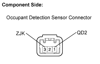 |
Disconnect the occupant detection sensor connector.
Measure the resistance.
| Tester Connection | Condition | Specified Condition |
| 1 (QD2) - 3 (ZJK) | Front passenger seat unoccupied | 10 kΩ or higher |
| 1 (QD2) - 3 (ZJK) | Front passenger seat occupied | Below 1Ω |
Reconnect the occupant detection sensor connector.
|
| ||||
| OK | |
|
| 9.CHECK HARNESS AND CONNECTOR (FRONT SEAT INNER BELT ASSEMBLY - COMBINATION METER ASSEMBLY) |
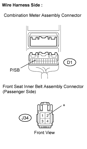 |
LHD:
Disconnect the J34 front seat inner belt assembly (passenger side) connector.
Disconnect the D1 combination meter assembly connector.
Measure the resistance.
| Tester Connection | Specified Condition |
| J34-2 (+) - D1-10 (P/SB) | Below 1Ω |
Reconnect the front seat inner belt assembly (passenger side) connector.
Reconnect the combination meter assembly connector.
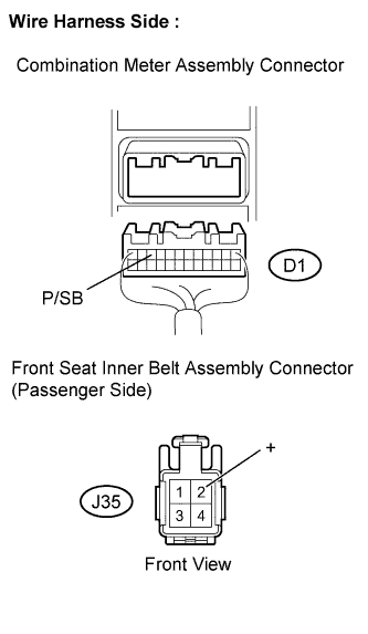 |
RHD:
Disconnect the J35 front seat inner belt assembly (passenger side) connector.
Disconnect the D1 combination meter assembly connector.
Measure the resistance.
| Tester Connection | Specified Condition |
| J35-2 (+) - D1-10 (P/SB) | Below 1Ω |
Reconnect the front seat inner belt assembly (passenger side) connector.
Reconnect the combination meter assembly connector.
|
| ||||
| OK | ||
| ||
| ||
| 10.READ VALUE USING INTELLIGENT TESTER (D DOOR COURTESY SW) |
Connect the intelligent tester to the DLC3.
Turn the ignition switch ON and turn the tester on.
Read the Data List according to the prompts displayed on the tester.
| Item | Measurement Item/Range (Display) | Normal Condition | Diagnostic Note |
| D Door Courtesy SW | Front door courtesy switch (Driver side) ON / OFF | ON: Front door open OFF: Front door close | - |
|
| ||||
| NG | |
|
| 11.INSPECT FRONT DOOR COURTESY SWITCH (DRIVER SIDE) |
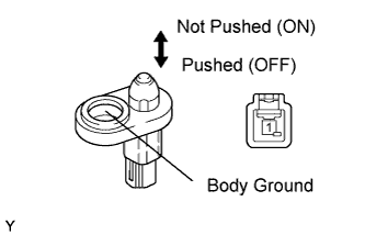 |
Disconnect the J2 front door courtesy switch connector.
Measure the resistance.
| Tester Connection | Condition | Specified Condition |
| J2-1 - Body ground | Not pushed (ON) | Below 1Ω |
| J2-1 - Body ground | Pushed (OFF) | 10 kΩ or higher |
Reconnect the front door courtesy switch connector.
|
| ||||
| OK | |
|
| 12.CHECK HARNESS AND CONNECTOR (FRONT DOOR COURTESY SWITCH - MAIN BODY ECU) |
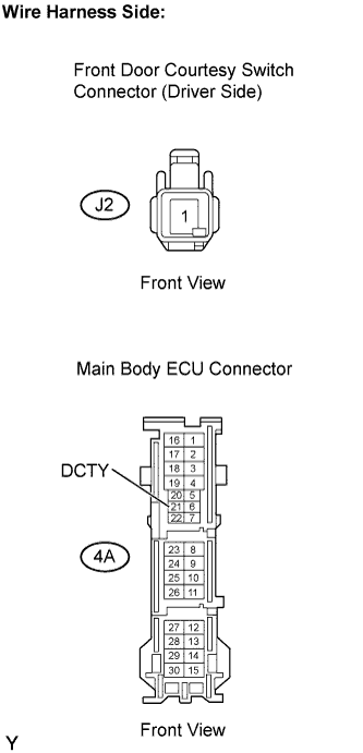 |
LHD:
Disconnect the J2 front door courtesy switch connector.
Disconnect the 4A main body ECU connector.
Measure the resistance.
| Tester Connection | Specified Condition |
| J2-1 - 4A-21 (DCTY) | Below 1Ω |
Reconnect the front door courtesy switch connector.
Reconnect the main body ECU connector.
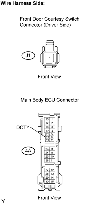 |
RHD:
Disconnect the J1 front door courtesy switch connector.
Disconnect the 4A main body ECU connector.
Measure the resistance.
| Tester Connection | Specified Condition |
| J1-1 - 4A-21 (DCTY) | Below 1Ω |
Reconnect the front door courtesy switch connector.
Reconnect the main body ECU connector.
|
| ||||
| OK | ||
| ||
| ||
| 13.INSPECT COMBINATION METER ASSEMBLY |
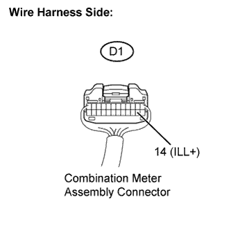 |
Disconnect the D1 combination meter assembly connector.
Measure the voltage.
| Tester Connection | Condition | Specified Condition |
| D1-14 (ILL+) - Body ground | Headlight dimmer switch tail or head position | 10 to 14 V |
Reconnect the combination meter assembly connector.
|
| ||||
| NG | |
|
| 14.CHECK HARNESS AND CONNECTOR (COMBINATION METER ASSEMBLY - MAIN BODY ECU) |
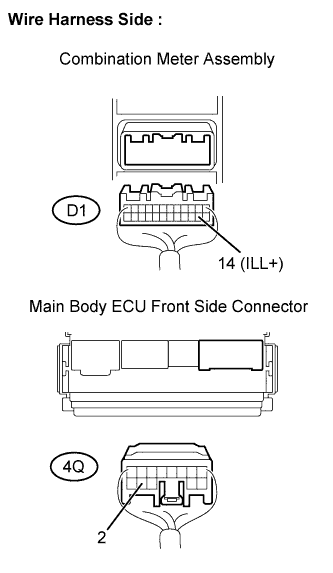 |
Disconnect the D1 combination meter assembly connector.
Disconnect the 4Q main body ECU connector.
Measure the resistance.
| Tester Connection | Specified Condition |
| D1-14 (ILL+) - 4Q-2 | Below 1 Ω |
Reconnect the combination meter assembly connector.
Reconnect the main body ECU connector.
|
| ||||
| OK | ||
| ||
| ||

