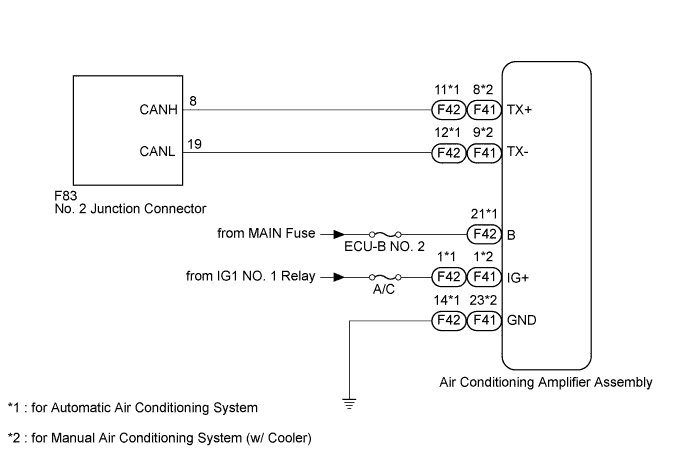
CAN COMMUNICATION SYSTEM (except Separate Type Yaw Rate Sensor) > Air Conditioning Amplifier Communication Stop Mode |
| Detection Item | Symptom | Trouble Area |
| Air Conditioning Amplifier Communication Stop Mode | Either condition is met:
|
|
| 1.CHECK FOR OPEN IN CAN BUS WIRE (AIR CONDITIONING AMPLIFIER ASSEMBLY BRANCH WIRE) |
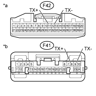 |
Disconnect the F42*1 or F41*2 air conditioning amplifier assembly connector.
Measure the resistance according to the value(s) in the table below.
| Tester Connection | Switch Condition | Specified Condition |
| F42-11 (TX+) - F42-12 (TX-)*1 F41-8 (TX+) - F41-9 (TX-)*2 | Ignition switch off | 54 to 69 Ω |
| *a | Front view of wire harness connector (to Air Conditioning Amplifier Assembly (for Automatic Air Conditioning System)) |
| *b | Front view of wire harness connector (to Air Conditioning Amplifier Assembly (for Manual Air Conditioning System (w/ Cooler))) |
|
| ||||
| OK | |
 |
| 2.CHECK HARNESS AND CONNECTOR (POWER SOURCE CIRCUIT) |
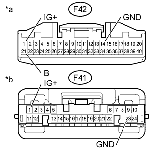 |
Measure the voltage according to the value(s) in the table below.
| Tester Connection | Switch Condition | Specified Condition |
| F42-1 (IG+) - Body ground*1 F41-1 (IG+) - Body ground*2 | Ignition switch ON | 11 to 14 V |
| F42-21 (B) - Body ground*1 | Always | 11 to 14 V |
Measure the resistance according to the value(s) in the table below.
| Tester Connection | Condition | Specified Condition |
| F42-14 (GND) - Body ground*1 F41-23 (GND) - Body ground*2 | Always | Below 1 Ω |
| *a | Front view of wire harness connector (to Air Conditioning Amplifier Assembly (for Automatic Air Conditioning System)) |
| *b | Front view of wire harness connector (to Air Conditioning Amplifier Assembly (for Manual Air Conditioning (w/ Cooler))) |
|
| ||||
| OK | ||
 | ||
| ||
