 |
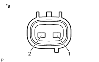
Measure the resistance according to the value(s) in the table below.
| *a | Component without harness connected (Transmission Revolution Sensor) |
- Standard Resistance:
Tester Connection Condition Specified Condition 1 - 2 20°C (68°F) 560 to 680 Ω
SPEED SENSOR (w/o ABS) > INSPECTION |
| 1. INSPECT TRANSMISSION REVOLUTION SENSOR |
|
Measure the resistance according to the value(s) in the table below.
| *a | Component without harness connected (Transmission Revolution Sensor) |
| Tester Connection | Condition | Specified Condition |
| 1 - 2 | 20°C (68°F) | 560 to 680 Ω |
| 2. INSPECT SPEEDOMETER SENSOR |
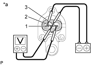 |
Connect the positive (+) lead from the battery to terminal 1 and the negative (-) lead to terminal 2.
| *a | Component without harness connected (Speedometer Sensor) |
Connect the positive (+) lead from the tester to terminal 3 and the negative (-) lead to terminal 2.
Rotate the shaft.
Check that the voltage output varies between 0 V and 11 V between terminals 2 and 3.