 |
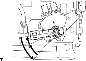
Turn the lever counterclockwise until it stops, then turn it clockwise 2 notches.
PARK / NEUTRAL POSITION SWITCH > INSTALLATION |
| 1. INSTALL PARK/NEUTRAL POSITION SWITCH ASSEMBLY |
Install the park/neutral position switch assembly to the automatic transaxle assembly.
Temporarily install the 2 bolts.
Replace the lock plate with a new one and install the nut, lock plate and washer.
Temporarily install the control shaft lever.
|
Turn the lever counterclockwise until it stops, then turn it clockwise 2 notches.
Remove the control shaft lever.
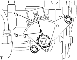 |
Align the groove and the neutral basic line.
| *a | Neutral Basic Line |
| *b | Groove |
Hold the switch in this position and tighten the 2 bolts.
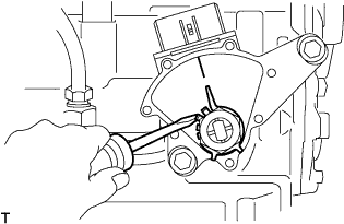 |
Using a screwdriver, stake the nut with the lock plate.
Install the control shaft lever with the nut and washer.
Connect the connector to the park/neutral position switch assembly.
| 2. INSTALL TRANSMISSION CONTROL CABLE ASSEMBLY |
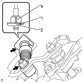 |
Install the transmission control cable assembly to the control shaft lever with the nut.
| *1 | No. 1 Transmission Control Cable Bracket |
| *2 | Clip |
| *a | Marking |
Install the transmission control cable assembly to the No. 1 transmission control cable bracket with a new clip.
| 3. ADJUST SHIFT LEVER POSITION |
| 4. INSPECT SHIFT LEVER POSITION |
Turn the ignition switch to ON and step on the brake pedal.
Confirm that the shift lever moves smoothly through all of the shift positions and the position indicator shows the correct shift lever position.
Start the engine and confirm that the vehicle moves forward when the shift lever is moved from N to D.
| 5. INSPECT PARK/NEUTRAL POSITION SWITCH ASSEMBLY |
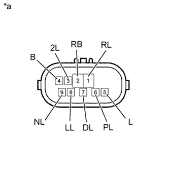 |
Measure the resistance according to the value(s) in the table below.
| *a | Component without harness connected (Park/Neutral Position Switch Assembly) |
| Tester Connection | Shift Position | Specified Condition |
| 4 (B) - 5 (L) | P or N | Below 1 Ω |
| Except P and N | 10 kΩ or higher | |
| 2 (RB) - 6 (PL) | P | Below 1 Ω |
| Except P | 10 kΩ or higher | |
| 1 (RL) - 2 (RB) | R | Below 1 Ω |
| Except R | 10 kΩ or higher | |
| 2 (RB) - 9 (NL) | N | Below 1 Ω |
| Except N | 10 kΩ or higher | |
| 2 (RB) - 7 (DL) | D and 3 | Below 1 Ω |
| Except D and 3 | 10 kΩ or higher | |
| 2 (RB) - 3 (2L) | 2 | Below 1 Ω |
| Except 2 | 10 kΩ or higher | |
| 2 (RB) - 8 (LL) | L | Below 1 Ω |
| Except L | 10 kΩ or higher |
| 6. INSTALL ENGINE UNDER COVER LH (for Plastic Type) |
| 7. INSTALL NO. 1 ENGINE UNDER COVER SUB-ASSEMBLY (for Metal Type) |