 |
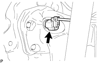
Using a screwdriver, disengage the claw of the connector lock portion and disconnect the skid control sensor wire LH connector.
- NOTICE:
- Do not remove the connector cover from the connector because the skid control sensor wire may be damaged.
REAR AXLE BEAM > REMOVAL |
| 1. REMOVE REAR WHEEL |
| 2. DRAIN BRAKE FLUID |
| 3. SEPARATE SKID CONTROL SENSOR WIRE LH (w/ ABS) |
|
Using a screwdriver, disengage the claw of the connector lock portion and disconnect the skid control sensor wire LH connector.
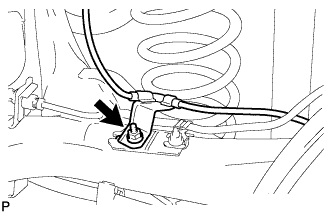 |
Remove the nut and separate the skid control sensor wire LH.
| 4. SEPARATE SKID CONTROL SENSOR WIRE RH (w/ ABS) |
| 5. SEPARATE NO. 4 REAR BRAKE TUBE |
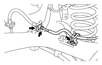 |
Using a union nut wrench (10 mm), separate the No. 4 rear brake tube while holding the rear flexible hose LH with a wrench.
Remove the clip and disconnect the rear flexible hose LH from the rear axle beam assembly.
Remove the nut and separate the No. 4 rear brake tube.
| 6. SEPARATE NO. 3 REAR BRAKE TUBE |
| 7. SEPARATE NO. 3 PARKING BRAKE CABLE ASSEMBLY |
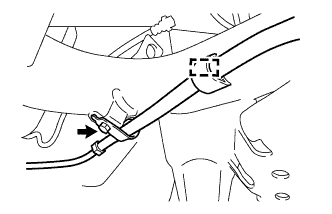 |
Remove the cable clamp from the rear axle beam assembly.
Remove the bolt and separate the No. 3 parking brake cable assembly.
Remove the cable clamp from the No. 3 parking brake cable assembly.
| 8. SEPARATE NO. 2 PARKING BRAKE CABLE ASSEMBLY |
| 9. REMOVE REAR BRAKE DRUM SUB-ASSEMBLY |
Release the parking brake and remove the rear brake drum.
If the rear brake drum cannot be removed easily, perform the following procedure.
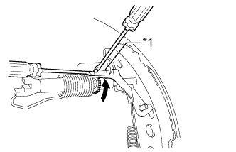 |
Remove the hole plug and insert a screwdriver through the hole into the backing plate, and hold the automatic adjust lever away from the adjuster.
| *1 | Automatic Adjust Lever |
 | Contract |
Using another screwdriver, contract the brake shoe by turning the adjusting bolt.
| 10. REMOVE REAR AXLE HUB AND BEARING ASSEMBLY |
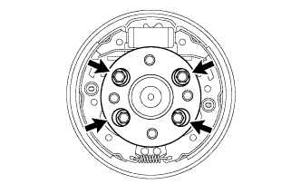 |
Remove the 4 bolts and remove the axle hub and bearing from the axle beam.
| 11. LOOSEN REAR AXLE BEAM ASSEMBLY |
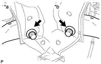 |
Loosen the 2 bolts.
| *a | RH Side |
| *b | LH Side |
| 12. SEPARATE REAR SHOCK ABSORBER ASSEMBLY LH |
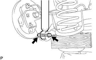 |
Support the rear axle beam assembly using a jack and wooden block as shown in the illustration.
Remove the bolt while keeping the nut from rotating and separate the rear shock absorber assembly LH.
| 13. SEPARATE REAR SHOCK ABSORBER ASSEMBLY RH |
| 14. REMOVE REAR COIL SPRING LH |
Lower the jack slowly.
Remove the rear coil spring LH, rear coil spring upper insulator LH and rear coil spring lower insulator LH.
| 15. REMOVE REAR COIL SPRING RH |
| 16. REMOVE REAR AXLE BEAM ASSEMBLY |
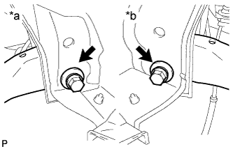 |
Remove the 2 bolts and rear axle beam assembly.
| *a | RH Side |
| *b | LH Side |