 |
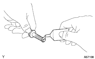
Apply adhesive to 2 or 3 threads on the end of the 4 bolts.
- Adhesive:
- Toyota Genuine Adhesive 1324, Three Bond 1324 or equivalent.
MANUAL TRANSAXLE ASSEMBLY > INSTALLATION |
| 1. INSTALL WIRE HARNESS CLAMP BRACKET |
Install the 3 wire harness clamp brackets with 3 bolts to the manual transaxle assembly.
| 2. INSTALL SPEEDOMETER DRIVEN HOLE COVER SUB-ASSEMBLY (w/ ABS) |
Coat a new O-ring with manual transaxle gear oil and install it to the speedometer driven hole cover sub-assembly.
Install the speedometer driven hole cover sub-assembly with the bolt.
| 3. INSTALL SPEEDOMETER SENSOR (w/o ABS) |
Coat a new O-ring with manual transaxle gear oil and install it to the speedometer sensor.
Install the speedometer driven gear to the speedometer sensor with the E-ring.
Install the speedometer sensor with the bolt.
| 4. INSTALL MANUAL TRANSAXLE ASSEMBLY |
Align the input shaft with the clutch disc and install the manual transaxle assembly to the engine assembly.
Install the 7 bolts.
| 5. INSTALL TRANSVERSE ENGINE ENGINE MOUNTING BRACKET |
Remove any adhesive remaining in the 4 bolts holes on the manual transaxle assembly and 4 bolts.
|
Apply adhesive to 2 or 3 threads on the end of the 4 bolts.
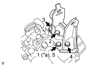 |
Following the procedures shown in the illustration, Tighten the 4 bolts in order.
| *a | Temporarily |
| 6. INSTALL TRANSVERSE ENGINE ENGINE MOUNTING INSULATOR |
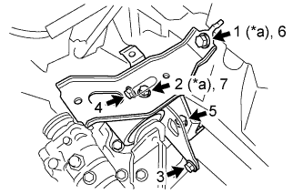 |
Following the procedures shown in the illustration, Tighten the 5 bolts in order.
Install the transverse engine engine mounting bracket and the transverse engine engine mounting insulator with the bolt and nut.
| 7. INSTALL TRANSVERSE ENGINE ENGINE MOUNTING CONTROL BRACKET |
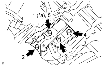 |
Following the procedures shown in the illustration, tighten the 4 bolts in order.
| *a | Temporarily |
| 8. INSTALL FRONT SUSPENSION CROSSMEMBER SUB-ASSEMBLY |
| 9. INSTALL FRONT DRIVE SHAFT ASSEMBLIES |
| 10. CONNECT WIRE HARNESS (w/ ABS) |
Connect the back up light switch connector.
Install the ground wire with the bolt.
Connect the 4 clamps and install the wire harness with the bolt.
| 11. CONNECT WIRE HARNESS (w/o ABS) |
Connect the speedometer sensor connector.
Connect the back up light switch connector.
Install the ground wire with the bolt.
Connect the 4 clamps and install the wire harness with the bolt.
| 12. INSTALL CONTROL CABLE BRACKET |
Install the control cable bracket with the 2 bolts.
| 13. INSTALL TRANSMISSION CONTROL CABLE ASSEMBLY |
Connect the 2 transmission control cable ends and install the 2 washers and the 2 clips.
Install 2 new clips onto the control cable bracket.
| 14. INSTALL CLUTCH RELEASE CYLINDER ASSEMBLY |
Install the clutch release cylinder assembly and the clutch pipe with the 4 bolts.
| 15. INSTALL STARTER ASSEMBLY (for 1NZ-FE) |
| 16. INSTALL STARTER ASSEMBLY (for 2NZ-FE) |
| 17. INSTALL BATTERY CARRIER (for LHD) |
Install the battery carrier with the 5 bolts.
Engage the 6 wire harness clamps and install the wire harness.
| 18. INSTALL BATTERY CARRIER (for RHD) |
Install the battery carrier with the 5 bolts.
Engage the 7 wire harness clamps and install the wire harness.
| 19. INSTALL BATTERY TRAY |
| 20. INSTALL BATTERY |
Install the battery onto the vehicle with the battery clamp.
Connect the cable to the battery terminal.
| 21. INSTALL AIR CLEANER BRACKET |
Install the air cleaner bracket with the 2 bolts.
Connect the wire harness clamp to the air cleaner bracket.
| 22. INSTALL AIR CLEANER ASSEMBLY |
Install the air cleaner case onto the air cleaner bracket with the 2 bolts.
Engage the clamp and connect the wire harness to the air cleaner case.
Install the air cleaner element onto the air cleaner case.
Install the air cleaner cap sub-assembly with No. 1 air cleaner hose onto the throttle body assembly.
Engage the 2 clamps and connect the air cleaner cap sub-assembly to the air cleaner case subassembly.
Tighten the hose clamp.
Connect the vacuum switching valve assembly connector.
Connect the mass air flow meter connector.
Engage the 2 clamps and connect the wire harness to the air cleaner cap sub-assembly and vacuum switching valve assembly.
Connect the No. 2 fuel vapor feed hose to the intake manifold.
Connect the fuel vapor feed hose assembly to the No. 1 air cleaner hose and vacuum switching valve assembly with the 2 hose clamps.
Engage the clamp and connect the fuel vapor feed hose assembly to the No. 1 air cleaner hose.
| 23. INSTALL OUTER COWL TOP PANEL (for LHD) |
Install the outer cowl top panel with the 8 bolts.
Engage the 2 clamps and install the wire harness.
| 24. INSTALL OUTER COWL TOP PANEL (for RHD) |
Install the outer cowl top panel with the 8 bolts.
Engage the 2 clamps and install the wire harness.
| 25. INSTALL INNER COWL TOP TO COWL BRACE (for LHD) |
Install the cowl top to cowl brace with the 2 bolts.
| 26. INSTALL INNER COWL TOP TO COWL BRACE (for RHD) |
Install the cowl top to cowl brace with the 2 bolts.
| 27. INSTALL FRONT NO. 1 VENTILATOR SEAL (for LHD) |
Engage the clip and install the front No. 1 ventilator seal.
| 28. INSTALL FRONT NO. 1 VENTILATOR SEAL (for RHD) |
Engage the clip and install the front No. 1 ventilator seal.
| 29. INSTALL FRONT AIR SHUTTER SEAL RH (for LHD) |
| 30. INSTALL FRONT AIR SHUTTER SEAL RH (for RHD) |
| 31. INSTALL FRONT WIPER MOTOR AND LINK |
| 32. ADD MANUAL TRANSAXLE OIL |
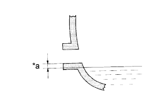 |
Add manual transmission oil until the oil level is within 5 mm (0.197 in.) from the bottom of the manual transmission filler plug opening.
| *a | 0 to 5 mm (0 to 0.197 in.) |
Check for oil leakage when the oil level is low.
Install the transmission filler plug and a new gasket.
| 33. INSPECT FOR MANUAL TRANSAXLE OIL |
|
| *a | 0 to 5 mm (0 to 0.197 in.) |
Stop the vehicle in a level place.
Remove the manual transmission filler plug and the gasket.
Check that the oil surface is within 5 mm (0.197 in.) of the bottom of the manual transmission filler plug opening.
Check for oil leakage when the oil level is low.
Install the manual transmission filler plug and a new gasket.
| 34. INSPECT FOR MANUAL TRANSAXLE OIL LEAK |