Terminal No. (Symbol)
| Wiring Color
| Terminal Description
| Condition
| Specified Condition
|
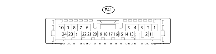
F41-1 (IG+) - F41-23 (GND)
| V - W-B
| Ignition power supply
| Ignition switch: ON
| 11 to 14 V
|
F41-2 (A/C) - F41-23 (GND)*1
| G - W-B
| A/C switch signal
| Ignition switch: ON
| Below 1 V → 11 to 14 V
|
Defroster: OFF
|
A/C switch: OFF → ON
|
Defroster mode detection switch signal
| Ignition switch: ON
| Below 1 V → 11 to 14 V
|
A/C switch: OFF
|
Defroster: OFF → ON
|
F41-3 (B/V) - F41-15 (SG- 1)*2
| SB - B
| Room temperature set signal
| Ignition switch: ON
| 4.5 to 5.5 V → Below 1 V
|
No. 3 heater control knob: MAX COOL
|
F41-4 (TE) - F41-15 (SG- 1)
| GR - B
| Evaporator temperature sensor signal
| Ignition switch: ON
| 1.0 to 1.3 V
|
Temperature near evaporator: 15°C (59°F)
|
F41-5 (SG-2) - Body ground
| L - Body ground
| Ground for ambient temperature sensor and A/ C pressure sensor
| Always
| Below 1 Ω
|
F41-7 (PRE) - F41-23 (GND)
| GR - W-B
| A/C pressure sensor signal
| Refrigerant pressure: Normal
| 0.63 to 4.73 V
|
Refrigerant pressure: Abnormal
(less than 0.176 MPaG [1.8 kgf/cm2] or more than 3.03 MPaG [31 kgf/cm2])
| Below 0.63 V or 4.73 V or more
|
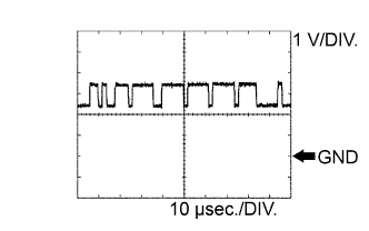
F41-8 (TX+) - F41-23 (GND)
| V - W-B
| CAN communication signal
| Ignition switch: ON
| Pulse generation
(See waveform 1)
|
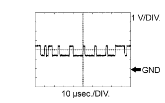
F41-9 (TX-) - F41-23 (GND)
| W - W-B
| CAN communication signal
| Ignition switch: ON
| Pulse generation
(See waveform 2)
|
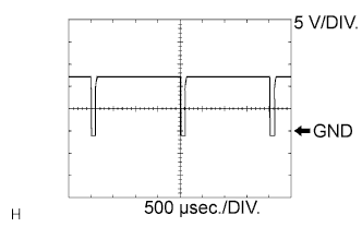
F41-11 (SOL+) - F41-23 (GND)
| P - W-B
| A/C compressor operation signal
| Engine idling
| Pulse generation
(See waveform 3)
|
Blower switch: 1
|
A/C switch: ON*1
|
No. 3 heater control knob: MAX COOL*2
|
F41-14 (HR) - Body ground
| R - Body ground
| Heater blower motor relay operation signal
| Ignition switch: ON
| 11 to 14 V → Below 1 V
|
Blower switch: 0 → 1
|
F41-15 (SG-1) - Body ground
| B - Body ground
| Ground for evaporator temperature sensor
| Always
| Below 1 Ω
|
F41-16 (LED) - Body ground*1
| BE - Body ground
| A/C switch indicator signal
| Engine idling
| 11 to 14 V → Below 4 V
|
A/C switch: ON
|
Blower switch: 0 → 1
|
F41-17 (SBLW) - Body ground
| GR - Body ground
| Blower motor ON signal
| Ignition switch: ON
| 11 to 14 V → Below 1 V
|
Blower switch: 0 → 1
|
F41-22 (TAM) - F41-5 (SG-2)
| W - L
| A/C ambient temperature sensor signal
| Ignition switch ON at 25°C (77°F)
| 1.35 to 1.75 V
|
F41-23 (GND) - Body ground
| W-B - Body ground
| Ground for main power supply
| Always
| Below 1 Ω
|
F41-24 (S5-3) - F41-23 (GND)
| Y - W-B
| Power supply for pressure sensor
| Ignition switch: ON
| 4.75 to 5.25 V
|