Home › Vehicle Interior › HEATING / AIR CONDITIONING › AIR CONDITIONING UNIT

AIR CONDITIONING UNIT > REASSEMBLY

for Preparation Click here


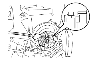
1. INSTALL NO. 1 COOLER THERMISTOR


    I103778E03
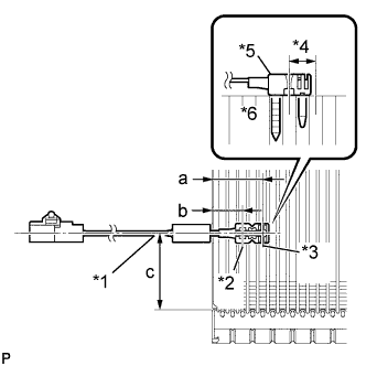
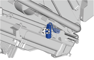
  1. Install the front evaporator temperature sensor (No. 1 cooler thermistor) as shown in the illustration.

    Installation Position:
    Mark
    Measurement
    a
    34.3 mm (1.35 in.)
    b
    20.9 mm (0.82 in.)
    c
    48 to 52 mm (1.890 to 2.047 in.)

    Text in Illustration 
    *1
    from Tank
    *2
    Fixed Part
    *3
    Sensor Part
    *4
    Next to Previous
    *5
    Plastic Case
    *6
    Evaporator

    NOTICE:
    1. Be sure to insert the sensor only once because reinserting it will not allow it to be firmly secured.
    2. When reusing the evaporator, insert the sensor one row next to the one that was used previously (*4 in the illustration).
    3. After inserting the sensor, do not apply excessive force to the wire.
    4. Directly insert the sensor until the edge of the plastic case "*5" comes into contact with the evaporator "*6".
2. INSTALL NO. 1 COOLER EVAPORATOR SUB-ASSEMBLY

HINT:
If a new cooler evaporator is installed, add compressor oil to the cooler evaporator as follows.

Capacity:
Add 40 cc (1.35 fl. oz.)

Compressor oil:
ND-OIL 8 or equivalent


    I100747
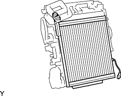
  1. Install the cooler evaporator with the cooler thermistor.


    I106197
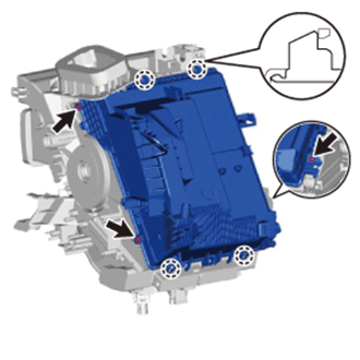
  1. Engage the 4 claws and install the lower heater case.

  1. Install the 3 screws.


    I106196
  1. Engage the clamp and install the connector to the lower heater case.


3. INSTALL DRAIN COOLER HOSE


    I106195
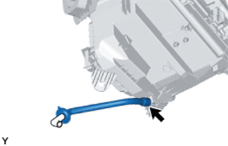
  1. Install the drain hose.


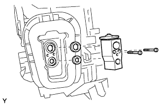
4. INSTALL COOLER EXPANSION VALVE


    I106123
  1. Sufficiently apply compressor oil to 2 new O-rings and the fitting surface of the No. 1 cooler evaporator.

    Compressor oil:
    ND-OIL 8 or equivalent

  1. Install the 2 O-rings to the cooler evaporator.

    NOTICE:
    Keep the O-rings and O-ring fitting surfaces clean from dirt or any foreign objects.

  1. Using a 4 mm hexagon wrench, install the cooler expansion valve with the 2 hexagon bolts.

    Torque:
    3.5 N*m{ 36 kgf*cm , 31 in.*lbf }


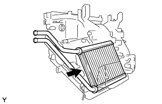
5. INSTALL HEATER RADIATOR UNIT SUB-ASSEMBLY


    I101202
  1. Install the radiator heater unit onto the air conditioning unit.


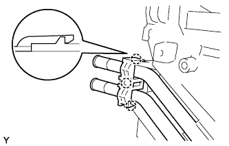
    I101620
  1. Engage the 3 claws and install the clamp.


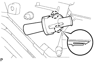
6. INSTALL ASPIRATOR PIPE (for Automatic Air Conditioning System)


    I105458
  1. Engage the 2 claws and install the aspirator pipe.


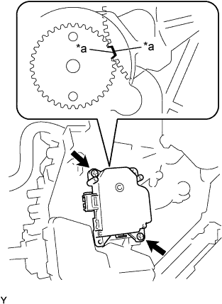
7. INSTALL NO. 1 AIR CONDITIONING RADIATOR DAMPER SERVO SUB-ASSEMBLY (for Automatic Air Conditioning System)


    I100736E05
  1. Align the reference position, and then install the air conditioning radiator damper servo.
    Text in Illustration 
    *a
    Reference Position

  1. Tighten the 2 screws.


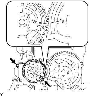
8. INSTALL NO. 2 AIR CONDITIONING RADIATOR DAMPER SERVO SUB-ASSEMBLY (for Automatic Air Conditioning System)


    I100734E05
  1. Align the reference position, and then install the air conditioning radiator damper servo.
    Text in Illustration 
    *a
    Reference Position

  1. Tighten the 2 screws.


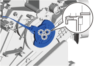
9. INSTALL AIR MIX DAMPER CONTROL CABLE SUB-ASSEMBLY (for Manual Air Conditioning System)


    I106289
  1. Engage the 3 claws and install the air mix damper control cable.


    I106193
  1. Install the plate.


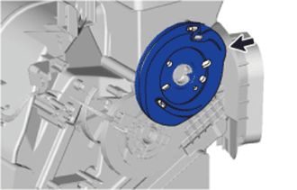
10. INSTALL DEFROSTER DAMPER CONTROL CABLE SUB-ASSEMBLY (for Manual Air Conditioning System)


    E163936
  1. Engage the 3 claws and install the defroster damper control cable.