 |
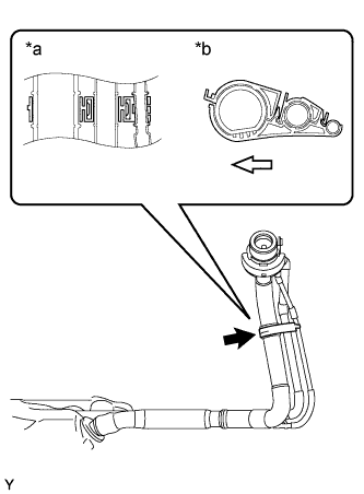
Install the fuel tank filler pipe support No. 3 in the position shown in the illustration.
| *a | Installation Position |
| *b | Cutaway View |
 | Front of Vehicle |
FUEL TANK > INSTALLATION |
| 1. INSTALL NO. 3 FUEL TANK FILLER PIPE SUPPORT |
|
Install the fuel tank filler pipe support No. 3 in the position shown in the illustration.
| *a | Installation Position |
| *b | Cutaway View |
| Front of Vehicle |
| 2. INSTALL NO. 1 FUEL TANK FILLER PIPE SUPPORT |
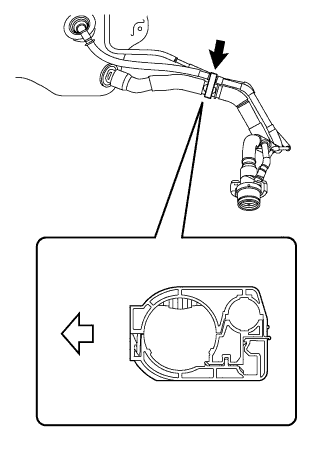 |
Install the No. 1 fuel tank filler pipe support in the position shown in the illustration.
| Out Side of Vehicle |
| 3. INSTALL NO. 2 FUEL TANK FILLER PIPE SUPPORT |
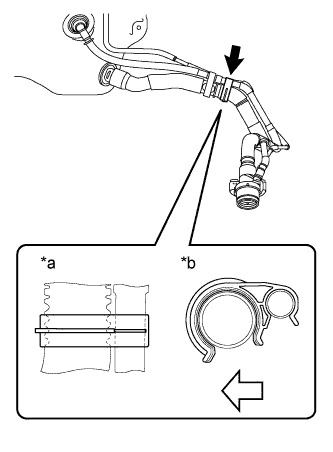 |
Install the No. 2 fuel tank filler pipe support in the position shown in the illustration.
| *a | Clamp Position |
| *b | Section |
| Out Side of Vehicle |
| 4. INSTALL FUEL HOSE CLAMP |
Install the fuel hose clamp onto the fuel tank assembly.
| 5. INSTALL NO. 1 CANISTER OUTLET HOSE SUB-ASSEMBLY |
Install the No. 1 canister outlet hose sub-assembly to the fuel tank assembly.
| 6. INSTALL NO. 2 FUEL EMISSION TUBE |
Install the No. 2 fuel emission tube into the groove of the fuel tank assembly.
| 7. INSTALL FUEL TANK MAIN TUBE SUB-ASSEMBLY |
Install the fuel tank main tube into the groove of the fuel tank assembly.
| 8. INSTALL FUEL TANK ASSEMBLY |
Clean and degrease the bolt holes.
Using an engine lifter, set the fuel tank assembly in the installation position.
Install the fuel tank assembly with 4 new bolts.
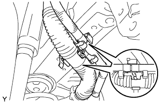 |
Assemble the 2 fuel hoses to the position shown in the illustration.
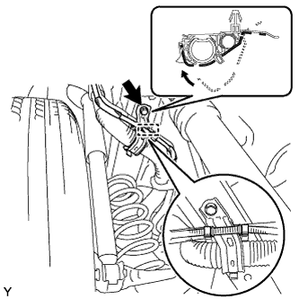 |
Install the fuel tank filler pipe flange plate as shown in the illustration.
Install the bolt.
Install the fuel tube.
| 9. CONNECT NO. 2 FUEL EMISSION TUBE |
Align the axis of the fuel tube connector and the axis of the pipe, and push in the fuel tube connector until the retainer makes a click sound.
After connecting the fuel tube connector, pull on the fuel tube connector and the pipe to make sure they are firmly connected.
| 10. CONNECT FUEL TANK MAIN TUBE SUB-ASSEMBLY |
Align the axis of the fuel tube connector and the axis of the pipe, and push in the fuel tube connector until the retainer makes a click sound.
After connecting the fuel tube connector, pull on the fuel tube connector and the pipe to make sure they are firmly connected.
Push the fuel tube connector cover in to lock it.
| 11. INSTALL FUEL TANK COVER VENT CASE SUB-ASSEMBLY |
Install the fuel tank cover vent case with the bolt and the clip.
| 12. INSTALL FRONT NO. 2 FLOOR HEAT INSULATOR |
Install the front No. 2 floor heat insulator with the 2 nuts.
| 13. ADD FUEL |
| 14. INSTALL FUEL SUCTION TUBE ASSEMBLY WITH PUMP AND GAUGE |