 |
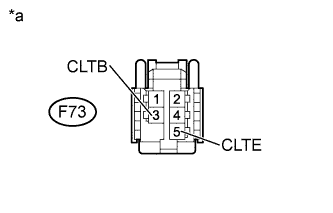
Disconnect the F73 solar sensor connector.
| *a | Front view of wire harness connector (to Solar Sensor) |
SOLAR SENSOR > INSPECTION |
| 1. INSPECT SOLAR SENSOR (AUTOMATIC LIGHT CONTROL SENSOR) |
|
Disconnect the F73 solar sensor connector.
| *a | Front view of wire harness connector (to Solar Sensor) |
Measure the voltage according to the value(s) in the table below.
| Tester Connection | Switch Condition | Specified Condition |
| F73-3 (CLTB) - F73-5 (CLTE) | Ignition switch off | Below 1 V |
| F73-3 (CLTB) - F73-5 (CLTE) | Ignition switch ON | 11 to 14 V |
Reconnect the solar sensor connector.
Turn the ignition switch to ON.
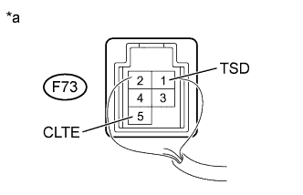 |
Measure the voltage according to the value(s) in the table below.
| *a | Component with harness connected (Solar Sensor) |
| Tester Connection | Condition | Specified Condition |
| F73-1(TSD) - F73-5(CLTE) | Without direct light exposure (Sensor covered) | Below 0.8 V |
| F73-1(TSD) - F73-5(CLTE) | When exposed to sunlight or an inspection light | 4.0 to 4.6 V |