 |
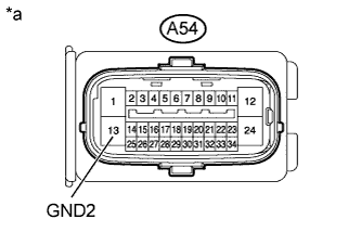
Measure the resistance according to the value(s) in the table below.
- Standard Resistance:
Tester Connection Condition Specified Condition A54-13 (GND2) - Body ground Always Below 1 Ω
| *a | Front view of wire harness connector (to Skid control ECU) |
DTC C1428 Motor Circuit Malfunction |
| DTC No. | DTC Detection Condition | Trouble Area |
| C1428 | With the ABS motor relay OFF and the ABS motor fail safe relay ON, an open in the motor circuit continues for 2 seconds or more. | Brake actuator assembly (Motor circuit) |
| 1.CHECK HARNESS AND CONNECTOR (GND2 TERMINAL) |
Disconnect the skid control ECU connector.
|
Measure the resistance according to the value(s) in the table below.
| Tester Connection | Condition | Specified Condition |
| A54-13 (GND2) - Body ground | Always | Below 1 Ω |
| *a | Front view of wire harness connector (to Skid control ECU) |
|
| ||||
| OK | ||
 | ||
| ||
